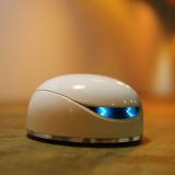
Vortex可编程机器人
![]()
Vortex
目录
1 简介
2 产品规格
3 主板硬件说明
4 表情板接口
5 示例代码及硬件详述
5.1 灰度传感器测试
5.1.1 灰度传感器原理及定型应用
5.1.2 灰度传感器位置图及对应ARUDINO引脚
5.1.3 样例代码
5.1.4 测试过程
5.2 红外壁障测试
5.2.1 红外壁障传感器原理及定型应用
5.2.2 红外壁障传感器位置图及对应的Arduino引脚
5.2.3 样例代码
5.2.4 测试过程
5.3 RGB灯测试
5.3.1 RGB灯原理及定型应用
5.3.2 RGB灯位置图及对应的Arduino引脚
5.3.3 样例代码
5.3.4 测试过程
5.4 mp3测试
5.4.1 mp3原理及定型应用
5.4.2 对应的Arduino引脚
5.4.3 样列代码
5.4.4 测试过程
5.5 电机驱动测试
5.5.1 电机驱动原理及定型应用
5.5.2 对应的Arduino引脚
5.5.3 样列代码
5.5.4 测试过程
5.6 编码器测试
5.6.1 编码器原理及定型应用
5.6.2 编码器位置图及对应的Arduino引脚
5.6.3 样例代码
5.6.4 测试过程
5.7 表情测试
5.7.1 表情板原理及定型引用
5.7.2 表情板位置及对应的Arduino引脚
5.7.3 样例代码
5.7.4 测试过程
6 更多
简介
Vortex通过配套App来让孩子学习基本的机器人及编码,同时有易用性界面。
Vortex集成一下主要部件:
2个 红外发射管
1个 红外接收管
2个 表情板
2个 小乌龟按钮(包括复位按键和boot按键)
12个 全彩RGB灯珠
6个 红外巡线传感器
2个 N20直流减速电机
1个 3w喇叭
1个 蓝牙芯片
2个 编码器
vortex为初学者提供8节课程,从入门到实现避障等测试,使用户通过教程轻松掌握。
表情板接口
灰度传感器测试
红外壁障测试
RGB灯测试
mp3测试
电机驱动测试
编码器测试
表情测试
产品规格
主控:Atmega 328p(兼容uno)
供电方式:AA电池*4或micro-USB供电
工作电压:3.5--6V
驱动方式:两轮差速驱动(优质mini型金属齿轮减速电机)
静态功耗:100mA
喇叭功率:3w
支持无线下载程序
主板硬件说明

![]() 主板硬件说明图
主板硬件说明图
灰度传感器:6个灰度传感器采用模拟量输入
蓝牙电路:CC2540f256芯片控制
N20电机:采用N20电机及1:75减速箱组成
电机驱动电路:双H桥驱动电路
壁障传感器:采用38KHz红外接收头
表情板接口:用于控制表情板及驱动两个红外发射管
电源电路:自适应升降压电路
顶板接口:采用间距1.27mm接口
编码器:2路编码传感器,用于检测轮子转速
电源接口:DC接口,输入电源电压范围3.5~6V
表情板接口
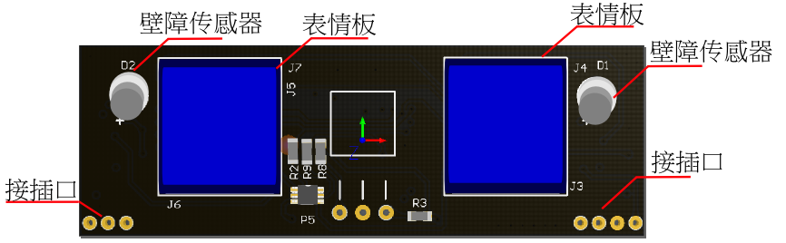
![]() 表情板接口
表情板接口
壁障传感器:2路红外发射管,用于左右壁障
表情板:5*5RGB点阵组成
接插口:插接在主板上
示例代码及硬件详述
灰度传感器测试
灰度传感器原理及定型应用
灰度传感器由一组红外发射接受管组成,利用不同颜色对红外光的反射程度不同,来鉴别颜色的深浅。在机器人领域中,可应用于轨迹巡线,边界防跌落功能等。
灰度传感器位置图及对应ARUDINO引脚
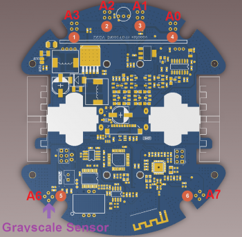
标号
管脚
1
A3
2
A2
3
A1
4
A0
5
A6
6
A7
样例代码
VORTEX Arduino 灰度传感器驱动代码:读取6个灰度传感器数值
![]()
请将顶板的Music/Program开关拨到Program端。
/***************************************************
Vortex V1.0 (Small robots like bread)
<http://www.dfrobot.com.cn/goods-1199.html>
This example show how to use Gray sensor on vortex.
Created 2016-2-3
By Andy zhou <Andy.zhou@dfrobot.com>
version:V1.0
****************************************************/
/***********Notice and Trouble shooting***************
1.Connection and Diagram can be found here
<http://wiki.dfrobot.com.cn/index.php?title=(SKU:ROB0116)_Vortex%E5%8F%AF%E7%BC%96%E7%A8%8B%E6%9C%BA%E5%99%A8%E4%BA%BA#.E6.A0.B7.E4.BE.8B.E4.BB.A3.E7.A0.81>
2.This code is tested on vortex V1.0.
****************************************************/
void setup(void){
Serial.begin(9600);
}
int analogBuf[6] = {'\0'};
void loop(void){
analogBuf[
<img alt="" src="http://images.ncnynl.com/arduino/2016/297px-ROB0116-RESUALT1.jpg" width="297" height="400" />
VORTEX摆放举例
<img alt="" src="http://images.ncnynl.com/arduino/2016/360px-ROB0116-RESUALT2.png" width="360" height="400" />
全部传感器都在白纸上
<img alt="" src="http://images.ncnynl.com/arduino/2016/360px-ROB0116-RESUALT3.png" width="360" height="400" />
第一个传感器在黑色胶带上,其余在白纸上
红外壁障测试
红外壁障传感器原理及定型应用
红外壁障传感器由两个红外发射管和接收管组成,发射管以38KHz频率连续发射20个脉冲,并在一定时间内检测接收到的脉冲数量,来判断小车距离障碍物的距离。在机器人领域中,可应用于避开障碍物等。
红外壁障传感器位置图及对应的Arduino引脚
<img alt="" src="http://images.ncnynl.com/arduino/2016/431px-壁障.png" width="431" height="400" />
红外传感器接收位置
<img alt="" src="http://images.ncnynl.com/arduino/2016/450px-壁障发射.png" width="450" height="151" />
红外传感器发射位置
样例代码
VORTEX Arduino 红外壁障传感器驱动代码:测试壁障效果
![]()
请将顶板的Music/Program开关拨到Program端。
/***************************************************
Vortex V1.0 (Small robots like bread)
<http://www.dfrobot.com.cn/goods-1199.html>
This example show how to use Infrared sensor to avoid obstacles.
Created 2016-2-3
By Andy zhou <Andy.zhou@dfrobot.com>
version:V1.0
****************************************************/
/***********Notice and Trouble shooting***************
1.Connection and Diagram can be found here
<http://wiki.dfrobot.com.cn/index.php?title=(SKU:ROB0116)_Vortex%E5%8F%AF%E7%BC%96%E7%A8%8B%E6%9C%BA%E5%99%A8%E4%BA%BA#.E6.A0.B7.E4.BE.8B.E4.BB.A3.E7.A0.81>
2.This code is tested on vortex V1.0.
****************************************************/
#define IR_IN 7//IR receiver pin
#define L_IR 8 //left ir transmitter pin
#define R_IR 12 //right ir transmitter pin
int count;
void leftSend38KHZ(void){//left ir transmitter sends 38kHZ pulse
int i;
for(i=0;i<24;i++){
digitalWrite(L_IR,LOW);
delayMicroseconds(8);
digitalWrite(L_IR,HIGH);
delayMicroseconds(8);
}
}
void rightSend38KHZ(void){//right ir transmitter sends 38kHZ pulse
int i;
for(i=0;i<24;i++){
digitalWrite(R_IR,LOW);
delayMicroseconds(8);
digitalWrite(R_IR,HIGH);
delayMicroseconds(8);
}
}
void pcint0Init(void){//init the interrupt
PCICR |= 1 << PCIE2;
PCMSK2 |= 1 << PCINT23;
}
ISR(PCINT2_vect){//motor encoder interrupt
count++;
}
void obstacleAvoidance(void){
char i;
count=0;
for(i=0;i<20;i++){ //left transmitter sends 20 pulses
leftSend38KHZ();
delayMicroseconds(600);
}
if(count>20){//if recieved a lot pulse , it means there's a obstacle
Serial.println("Left");
delay(100);
}
count=0;
for(i=0;i<20;i++){//right transmitter sends 20 pulses
rightSend38KHZ();
delayMicroseconds(600);
}
if(count>20){//if recieved a lot pulse , it means there's a obstacle
Serial.println("Right");
delay(100);
}
}
void setup(void){
pinMode(L_IR,OUTPUT);//init the left transmitter pin
pinMode(R_IR,OUTPUT);//init the right transmitter pin
pinMode(IR_IN,INPUT);//init the ir receiver pin
Serial.begin(9600);
pcint0Init();
sei(); //enable the interrupt
}
void loop(void){
obstacleAvoidance();
}
<img alt="" src="http://images.ncnynl.com/arduino/2016/450px-壁障效果.png" width="450" height="209" />
避障接收
RGB灯测试
RGB灯原理及定型应用
RGB灯带是用6个内置IC芯片的RGB灯珠组成,通过单总线控制灯带颜色及亮度。在机器人领域中,可让小车更加炫酷。
RGB灯位置图及对应的Arduino引脚
RGB灯分布:主板6个+顶板6个,采用单线数据控制,控制口连接到uno的D13
![]()
相关库文件下载:Vortex库文件
样例代码
测试代码如下:
/***************************************************
Vortex V1.0 (Small robots like bread)
<http://www.dfrobot.com.cn/goods-1199.html>
This example show how to use RGB-leds.
Created 2016-2-3
By Andy zhou <Andy.zhou@dfrobot.com>
version:V1.0
****************************************************/
/***********Notice and Trouble shooting***************
1.Connection and Diagram can be found here
<http://wiki.dfrobot.com.cn/index.php?title=(SKU:ROB0116)_Vortex%E5%8F%AF%E7%BC%96%E7%A8%8B%E6%9C%BA%E5%99%A8%E4%BA%BA#.E6.A0.B7.E4.BE.8B.E4.BB.A3.E7.A0.81>
2.This code is tested on vortex V1.0.
****************************************************/
// Use if you want to force the software SPI subsystem to be used for some reason (generally, you don't)
// #define FORCE_SOFTWARE_SPI
// Use if you want to force non-accelerated pin access (hint: you really don't, it breaks lots of things)
// #define FORCE_SOFTWARE_SPI
// #define FORCE_SOFTWARE_PINS
#include "FastLED.h"
///////////////////////////////////////////////////////////////////////////////////////////
//
// Move a white dot along the strip of leds. This program simply shows how to configure the leds,
// and then how to turn a single pixel white and then off, moving down the line of pixels.
//
// How many leds are in the strip?
#define NUM_LEDS 12
// Data pin that led data will be written out over
#define DATA_PIN 13
// Clock pin only needed for SPI based chipsets when not using hardware SPI
//#define CLOCK_PIN 8
// This is an array of leds. One item for each led in your strip.
CRGB leds[NUM_LEDS];
// This function sets up the ledsand tells the controller about them
void setup() {
// sanity check delay - allows reprogramming if accidently blowing power w/leds
delay(2000);
// Uncomment one of the following lines for your leds arrangement.
// FastLED.addLeds<TM1803, DATA_PIN, RGB>(leds, NUM_LEDS);
// FastLED.addLeds<TM1804, DATA_PIN, RGB>(leds, NUM_LEDS);
// FastLED.addLeds<TM1809, DATA_PIN, RGB>(leds, NUM_LEDS);
FastLED.addLeds<WS2811, DATA_PIN, RGB>(leds, NUM_LEDS);
// FastLED.addLeds<WS2812, DATA_PIN, RGB>(leds, NUM_LEDS);
// FastLED.addLeds<WS2812B, DATA_PIN, RGB>(leds, NUM_LEDS);
// FastLED.addLeds<NEOPIXEL, DATA_PIN>(leds, NUM_LEDS);
// FastLED.addLeds<WS2811_400, DATA_PIN, RGB>(leds, NUM_LEDS);
// FastLED.addLeds<GW6205, DATA_PIN, RGB>(leds, NUM_LEDS);
// FastLED.addLeds<GW6205_400, DATA_PIN, RGB>(leds, NUM_LEDS);
// FastLED.addLeds<UCS1903, DATA_PIN, RGB>(leds, NUM_LEDS);
// FastLED.addLeds<UCS1903B, DATA_PIN, RGB>(leds, NUM_LEDS);
// FastLED.addLeds<WS2801, RGB>(leds, NUM_LEDS);
// FastLED.addLeds<SM16716, RGB>(leds, NUM_LEDS);
// FastLED.addLeds<LPD8806, RGB>(leds, NUM_LEDS);
// FastLED.addLeds<P9813, RGB>(leds, NUM_LEDS);
// FastLED.addLeds<WS2801, DATA_PIN, CLOCK_PIN, RGB>(leds, NUM_LEDS);
// FastLED.addLeds<SM16716, DATA_PIN, CLOCK_PIN, RGB>(leds, NUM_LEDS);
// FastLED.addLeds<LPD8806, DATA_PIN, CLOCK_PIN, RGB>(leds, NUM_LEDS);
}
// This function runs over and over, and is where you do the magic to light
// your leds.
void loop() {
// Move a single white led
for(int whiteLed = 0; whiteLed < NUM_LEDS; whiteLed = whiteLed + 1) {
// Turn our current led on to white, then show the leds
leds[whiteLed] = CRGB::White;
// Show the leds (only one of which is set to white, from above)
FastLED.show();
// Wait a little bit
delay(100);
// Turn our current led back to black for the next loop around
leds[whiteLed] = CRGB::Black;
}
}
<img alt="RGB white.png" src="http://images.ncnynl.com/arduino/2016/350px-RGB_white.png" width="350" height="400" />
mp3测试
mp3原理及定型应用
mp3控制端口采用模拟Serial与mp3通信,控制mp3播放功能
内置24种音乐
支持USB在线拷贝mp3文件,拷贝方法是:将顶板的切换开关切换到music端,插上电脑拷贝即可。
对应的Arduino引脚
通过D11引脚与mp3相连
样列代码
测试代码如下:
/***************************************************
Vortex V1.0 (Small robots like bread)
<http://www.dfrobot.com.cn/goods-1199.html>
This example show how to device mp3 player.
Created 2016-2-3
By Andy zhou <Andy.zhou@dfrobot.com>
version:V1.0
****************************************************/
/***********Notice and Trouble shooting***************
1.Connection and Diagram can be found here
<http://wiki.dfrobot.com.cn/index.php?title=(SKU:ROB0116)_Vortex%E5%8F%AF%E7%BC%96%E7%A8%8B%E6%9C%BA%E5%99%A8%E4%BA%BA#.E6.A0.B7.E4.BE.8B.E4.BB.A3.E7.A0.81>
2.This code is tested on vortex V1.0.
****************************************************/
#include <SoftwareSerial.h>
#include <VortexMp3.h>
#define MP3_VOLUME 0x10
void init(){
mp3.Init();
mp3.setVolume(MP3_VOLUME);
}
void setup() {
// put your setup code here, to run once:
init();
}
static int musicState = 1;
void loop(){
// put your main code here, to run repeatedly:
mp3.player(musicState);
musicState++;
if (musicState>=20){
musicState = 1;
}
delay(1000);
}
电机驱动测试
电机驱动原理及定型应用
通过4个I/O口,就能够控制小车的前进、后退、转弯、PWM调速的功能
对应的Arduino引脚
左轮:使能端连接uno的D5(高电平有效),方向控制端连接uno的D9(高电平正转,低电平反转)
右轮:使能端连接uno的D6(高电平有效),方向控制端连接uno的D10(高电平正转,低电平反转)
样列代码
示例代码如下:
/***************************************************
Vortex V1.0 (Small robots like bread)
<http://www.dfrobot.com.cn/goods-1199.html>
let the robots move.
Created 2016-2-3
By Andy zhou <Andy.zhou@dfrobot.com>
version:V1.0
****************************************************/
/***********Notice and Trouble shooting***************
1.Connection and Diagram can be found here
<http://wiki.dfrobot.com.cn/index.php?title=(SKU:ROB0116)_Vortex%E5%8F%AF%E7%BC%96%E7%A8%8B%E6%9C%BA%E5%99%A8%E4%BA%BA#.E6.A0.B7.E4.BE.8B.E4.BB.A3.E7.A0.81>
2.This code is tested on vortex V1.0.
****************************************************/
void setup() {
pinMode(5,OUTPUT);
pinMode(9,OUTPUT);
pinMode(6,OUTPUT);
pinMode(10,OUTPUT);
}
void loop() {
digitalWrite(5,HIGH);
digitalWrite(9,HIGH);
digitalWrite(6,HIGH);
digitalWrite(10,HIGH);
delay(2000);
digitalWrite(5,HIGH);
digitalWrite(9,LOW);
digitalWrite(6,HIGH);
digitalWrite(10,LOW);
delay(2000);
}
编码器测试
编码器原理及定型应用
编码器是采用红外发射式传感器,将电机转速转换成数字信号的传感器。在机器人领域中,可以测得小车的具体转速
编码器位置图及对应的Arduino引脚
左轮编码器:连接uno中断口0,即数字引脚D2
右轮编码器:连接uno中端口1,即数字引脚D3
<img alt="" src="http://images.ncnynl.com/arduino/2016/384px-编码器位置.png" width="384" height="400" />
编码器位置图
样例代码
/***************************************************
Vortex V1.0 (Small robots like bread)
<http://www.dfrobot.com.cn/goods-1199.html>
This example show how to use encoder sensor.
Created 2016-2-3
By Andy zhou <Andy.zhou@dfrobot.com>
version:V1.0
****************************************************/
/***********Notice and Trouble shooting***************
1.Connection and Diagram can be found here
<http://wiki.dfrobot.com.cn/index.php?title=(SKU:ROB0116)_Vortex%E5%8F%AF%E7%BC%96%E7%A8%8B%E6%9C%BA%E5%99%A8%E4%BA%BA#.E6.A0.B7.E4.BE.8B.E4.BB.A3.E7.A0.81>
2.This code is tested on vortex V1.0.
****************************************************/
#define pinInputLeft 0
#define pinInputRight 1
long leftPul,rightPul;
void leftCallBack(){
leftPul++;
}
void rightCallBack(){
rightPul++;
}
void initDdevice(){
pinMode(5,OUTPUT);
pinMode(6,OUTPUT);
pinMode(9,OUTPUT);
pinMode(10,OUTPUT);
attachInterrupt(pinInputLeft,leftCallBack,CHANGE);
attachInterrupt(pinInputRight,rightCallBack,CHANGE);
sei();
}
void motorDebug(){
digitalWrite(5,HIGH);
digitalWrite(6,HIGH);
digitalWrite(9,HIGH);
digitalWrite(10,HIGH);
}
void printPul(){
Serial.print(leftPul);
Serial.print(" ");
Serial.println(rightPul);
leftPul = 0;
rightPul = 0;
}
void setup() {
initDdevice();
Serial.begin(9600);
motorDebug();
}
void loop() {
printPul();
delay(500);
}
<img alt="" src="http://images.ncnynl.com/arduino/2016/450px-编码器效果图.png" width="450" height="205" />
编码器效果图
表情测试
表情板原理及定型引用
表情板采用两个5*5 RGB点阵屏组成,通过IIC发送命令控制表情。在机器人应用领域中,可以让小车显示各种表情
表情板位置及对应的Arduino引脚
<img alt="" src="http://images.ncnynl.com/arduino/2016/450px-表情板显示屏.png" width="450" height="196" />
表情板位置图
样例代码
/***************************************************
Vortex V1.0 (Small robots like bread)
<http://www.dfrobot.com.cn/goods-1199.html>
This example show how to use Gray sensor on vortex.
Created 2016-2-3
By Andy zhou <Andy.zhou@dfrobot.com>
version:V1.0
****************************************************/
/***********Notice and Trouble shooting***************
1.Connection and Diagram can be found here
<http://wiki.dfrobot.com.cn/index.php?title=(SKU:ROB0116)_Vortex%E5%8F%AF%E7%BC%96%E7%A8%8B%E6%9C%BA%E5%99%A8%E4%BA%BA#.E6.A0.B7.E4.BE.8B.E4.BB.A3.E7.A0.81>
2.This code is tested on vortex V1.0.
****************************************************/
#include <Wire.h>
#define I2C_LED_ADDRESS 0b1100000
#define I2C_WRITE 0x00
uint8_t serial=0;
void setup(){
Wire.begin(); // join i2c bus (address optional for master)
}
void loop(){
Wire.beginTransmission(I2C_LED_ADDRESS << 1 | I2C_WRITE); // transmit to device #4
Wire.write(0x01);
Wire.write(serial);
/*Wire.write(0x55);
Wire.write(0xAA);
Wire.write(0x07); //color set
//1 2 3 4 5 25 24 23 22 21
//6 7 8 9 10 20 19 18 17 16
//11 12 13 14 15 15 14 13 12 11
//16 17 18 19 20 10 9 8 7 6
//21 22 23 24 25 5 4 3 2 1
Wire.write(0x07);
Wire.write(0x18);
Wire.write(0x00);
Wire.write(0x04);
Wire.write(0x00);
Wire.write(0x07);
Wire.write(0x18);
Wire.write(0x00);
Wire.write(0x04);
Wire.write(0x00);
Wire.endTransmission(); // stop transmitting
serial++;
if(serial==35) serial=0;
delay(500);
}
更多
![]() [Link ]
[Link ]
|}