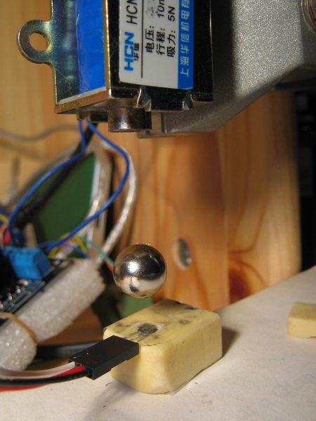
Arduino上拉磁悬浮
johnsonzzd 于 2012-12-9 16:59 编辑
折腾了几天终于把这个东西搞定了。看似简单,还是有一些小技巧的。
主要材料:
Arduino UNO主控SS495线性霍尔采集位置信息L298N驱动直径12.7mm强磁球电磁铁12V,线圈电阻10欧
主要参数:PID控制,采样周期1ms,PWM频率 3921Hz,悬浮距离30mm,电流300mA
筷子版的,下面是一个磁体,上面是一个小铁块,中间是一截筷子。悬浮距离比较小,但是方便进行建模和控制理论分析。

2012-5-22 18:12 上传
(149.8 KB)
磁球版,悬浮距离很大,不容易进行理论分析。

2012-5-22 18:12 上传
(96.95 KB)
ARDUINO 代码复制打印
const int SS495_PIN = A0;// Analog input pin that the SS495 is attached toconst int PWM_PIN=3;// Pins 3 and 11 are connected to Timer 2.const int SampleTime=600;const int PWM_BIAS=128;int Setpoint=850;double Kp=1, Ki=0.001, Kd=50;void setupCoilPWM(){ // Setup the timer 2 as Phase Correct PWM, 3921 Hz. pinMode(3, OUTPUT); // Timer 2 register: WGM20 sets PWM phase correct mode, COM2x1 sets the PWM out to channels A and B. TCCR2A = 0; TCCR2A = _BV(COM2A1) | _BV(COM2B1) | _BV(WGM20); // Set the prescaler to 8, the PWM freq is 16MHz/255/2/<prescaler> TCCR2B = 0; TCCR2B = _BV(CS21);}void writeCoilPWM(uint8_t pin, int val){ OCR2B = val;}void PID_Compute( ){static int lastError=0;static unsigned long int lastTime=0;static double iiterm=0;unsigned long now,timeChange;int input,output,error,piterm,diterm;now = micros();timeChange = (now - lastTime);if(timeChange>=SampleTime){ lastTime = now; input=read_input(); error = -(Setpoint - input); iiterm+= (Ki * error); iiterm=constrain(iiterm,-255,255); piterm=Kp * error; diterm=Kd * (error - lastError)1000/timeChange; output = PWM_BIAS+(piterm + diterm); output=constrain(output,0,255); writeCoilPWM(PWM_PIN, output); // print the results to the serial monitor: //sprintf(str,"%04d,%+04d,%+04d,%+04d,%04d",error,piterm,diterm,(int)iiterm,output); //Serial.println(str); /Remember some variables for next time*/ lastError = error; }}int read_input(){static int last=0;int r;r=analogRead(SS495_PIN);if(abs(r-last)<4) r=last;else last=r;return r;}void setup() {setupCoilPWM();}void loop() {// read the analog in value:PID_Compute();}const int SS495_PIN = A0;// Analog input pin that the SS495 is attached to下一步准备加上串口通讯,用matlab做上位机界面。已经做好了Arduino的自平衡车和两旋翼模型,有空也放上来。
const int PWM_PIN=3;// Pins 3 and 11 are connected to Timer 2.
const int SampleTime=600;
const int PWM_BIAS=128;
int Setpoint=850;
double Kp=1, Ki=0.001, Kd=50;
void setupCoilPWM()
{
// Setup the timer 2 as Phase Correct PWM, 3921 Hz.
pinMode(3, OUTPUT);
// Timer 2 register: WGM20 sets PWM phase correct mode, COM2x1 sets the PWM out to channels A and B.
TCCR2A = 0;
TCCR2A = _BV(COM2A1) | _BV(COM2B1) | _BV(WGM20);
// Set the prescaler to 8, the PWM freq is 16MHz/255/2/<prescaler>
TCCR2B = 0;
TCCR2B = _BV(CS21);
}
void writeCoilPWM(uint8_t pin, int val)
{
OCR2B = val;
}
void PID_Compute( )
{
static int lastError=0;
static unsigned long int lastTime=0;
static double iiterm=0;
unsigned long now,timeChange;
int input,output,error,piterm,diterm;
now = micros();
timeChange = (now - lastTime);
if(timeChange>=SampleTime)
{
lastTime = now;
input=read_input();
error = -(Setpoint - input);
iiterm+= (Ki * error);
iiterm=constrain(iiterm,-255,255);
piterm=Kp * error;
diterm=Kd * (error - lastError)1000/timeChange;
output = PWM_BIAS+(piterm + diterm);
output=constrain(output,0,255);
writeCoilPWM(PWM_PIN, output);
// print the results to the serial monitor:
//sprintf(str,"%04d,%+04d,%+04d,%+04d,%04d",error,piterm,diterm,(int)iiterm,output);
//Serial.println(str);
/Remember some variables for next time*/
lastError = error;
}
}
int read_input()
{
static int last=0;
int r;
r=analogRead(SS495_PIN);
if(abs(r-last)<4)
r=last;
else
last=r;
return r;
}
void setup() {
setupCoilPWM();
}
void loop() {
// read the analog in value:
PID_Compute();
}
自平衡车就在这里:
http://www.geek-workshop.com/thread-2398-1-1.html
单旋翼实验装置,已经发到amobbs了,有详细资料:
http://www.amobbs.com/thread-5505843-1-1.html
via - 极客工坊