传感器数据采集模块(转RS485输出)
<img alt="" src="http://images.ncnynl.com/arduino/2016/200px-IGP9854.jpg" width="200" height="200" class="thumbimage" /> <img src="http://images.ncnynl.com/arduino/2016/magnify-clip.png" width="15" height="11" alt="" />DFR0233
目录
1 产品简介
2 应用领域
3 技术规格
4 输出引脚
4.1 详细解析
5 产品指令
6 连接图
7 示例代码
产品简介
传感器数据采集模块(RS485输出)是DFRobot独家开发的传感器信息采集模块,能够将采集的数据转化成RS485协议数据,再传输到其他设备。该模块能够广泛的应用在智能农业、环境监测和智能家居等领域,能够100%兼容时下最流行的物联网设计。通过互联网和该模块能够实现设备与设备,设备与人之间的无缝对接,实现智能网络控制。它会成为你实施物联网项目的一大利器。
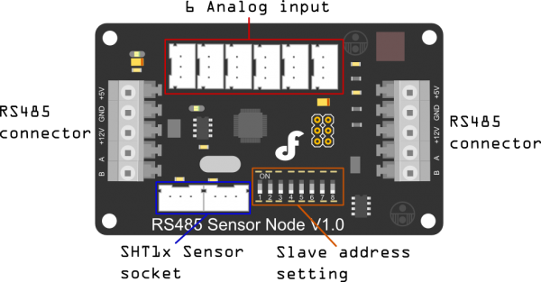
目前该款产品拥有6通道模拟信号输入和1个SHT1x 温湿度数字输入口,通过模块中的芯片转化成RS485信号,最终由两端的端口输出。通过该设备,可以轻松实现多个点对点、长距离数据通信。只要一个RS485输出口,你就可以监控多个传感器的模拟信号。
由于RS485标准能够在复杂的电磁环境下长距离、高效率地传输信号。通过RS485,多个接收设备能够通过单线链接到拥有多个节点的网络中。RS485标准的这一特性使得这类的网络在工业和民用环境中得到了广泛的应用。它还能够整合一些本地的网络和多点通信线路。该通信模式能够提供10米内35M/S和1200米时100KB/S的传输速度。
R485同时也是目前工业领域中最为重要的通讯方式。相比老式的RS232总线,RS485能实现更远的通讯距离和更加低廉的成本。目前物联网技术能够利用以太网络来整合RS485,然后利用广泛普及的以太网络,来实现各项设备之间的联网。
应用领域
智能化农业
公共安全监管
环境监控
个人医疗监护
智能家居
技术规格
MCU:ATmega8
输入电压:12v
多节点链接:能够与127个模块链接
人性化按键接线柱:简单、快速链接
1个 SHT1x温湿度传感器接口
6个 模拟传感器接口
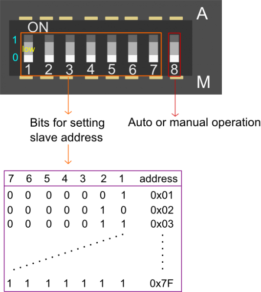
8个开关,用于直接设置从站地址
AD位数:10bit
模块采样速率:65 ~ 260 μs
湿度感应范围:0-100%(±4.5%误差)
温度感应范围:-40-128.8'C(±0.5℃)
尺寸:82*50mm
输出引脚
 DFR0233
详细解析
 DFR0233
手动或自动操作:该位是由软件或硬件设置的地址的从属设备.
A:通过软件设定的从机地址, , 当它是在A侧设置从属地址位将是无效的.
M:通过硬件设置的从机地址,当它在M侧经由7小switches.Success的设置30秒后,您可以设置从机地址 .
从站位设置地址:0x01~0x7F,仅仅是有效的为M侧
产品指令
检查当前所有的实时数据的指令 - 0X21
命令:
字头
设备地址
帧长度
命令字
校验
0x55
0xAA
0x11
0x00
0x21
SUM
此命令将检查所有的数据当前设备.那里的,全部的10寄存器数据.A的寄存器数据是16位,其中包括8个高四位和低8位数字.
以下返回:
内容顺序
注册说明
寄存器数据
注册范围
1
手动/自动设定地址状态
0x00 0x01
1 自动; 0 手动
2
湿度测量
0x00 0x02
0.0 to 100.0%(RH)
3
温度测量
0x00 0x03
-40.0 to 128.0(℃)
4
SHT1X错误状态
0x00 0x04
1 for error; 0 for normal
5
模拟测量 1
0x00 0x05
0 to 1023
6
模拟测量 2
0x00 0x06
0 to 1023
7
模拟测量 3
0x00 0x07
0 to 1023
8
模拟测量 4
0x00 0x08
0 to 1023
9
模拟测量 5
0x00 0x09
0 to 1023
10
模拟测量 6
0x00 0x10
0 to 1023
指令说明:内容值由2个字节;0.0〜100.0度为0到1000的立场;-40.0128.0度-400到1280架.
返回值:
字头
设备地址
帧长度
命令字
内容
校验
0x55
0xAA
0x11
0x14
0x21
H
T
SUM
示例:
发送指令:
字头
设备地址
帧长度
命令字
校验
0x55
0xAA
0x11
0x00
0x21
0x31
返回指令:
字头
设备地址
帧长度
命令字
内容1
内容2
内容3
0x55
0xAA
0x11
0x14
0x21
0x00 0x00
0x00 0x00
0x00 0x00
内容4
内容5
内容6
内容7
内容8
内容9
内容10
校验
0x00 0x01
0x00 0x66
0x00 0x99
0x00 0x66
0x00 0x99
0x00 0x66
0x00 0x99
0x46
设置地址的模式是 --0x55
命令:
字头
设备地址
帧长度
命令字
内容
校验
0x55
0xAA
0xAB
0x01
0x55
0x22
SUM
返回值:
字头
设备地址
帧长度
命令字
内容
校验
0x55
0xAA
0xAB
0x01
0x55
0x22
SUM
指令说明:是0xAB是广播地址,也就是说,它是所有车型共享地址。发送0x55的到的是0xAB中为了设置模型模型不确定状态地址解决
根据新的设备地址,型号将返回0x55的地址后,设置成功;在手动状态,发送0x55的不能设置当前设备的地址,如果该产品可以手动设置设备地址和automatically.Then的,返回值是0XFE说明产品在手动设定地址的状态. 返回值:字头
设备地址
帧长度
命令字
内容
校验
0x55
0xAA
0xAB
0x01
0x55
0xFF
SUM
示例:
发送指令:
字头
设备地址
帧长度
命令字
内容
校验
0x55
0xAA
0xAB
0x01
0x55
0x11
0x11
此示例中,用于设备的地址设置为0x11.
手动设置地址的状态
发送指令:
字头
设备地址
帧长度
命令字
内容
校验
0x55
0xAA
0xAB
0x01
0x55
0x11
0x11
返回指令:
字头
设备地址
帧长度
命令字
内容
校验
0x55
0xAA
0xAB
0x01
0x55
0xFF
0xFF
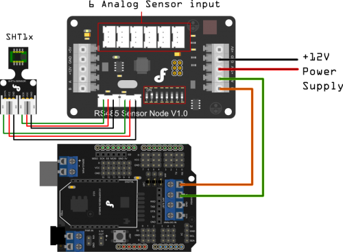
连接图
 DFR0233
示例代码
/*
The Sample code for test the data of Analogue_Test and SHT1X Module
Editor : Phoebe
Date : 2012.10.25
Ver : 0.2
Product: Analogue_Test and SHT1X Module
SKU :
Description:
Read the Analog value and the data of humidity & temperature
Hardwares:
- Arduino UNO
- IO Expansion Shield V5
- Analogue_Test and SHT1X Module
Interface: RS485
Note: Connect the Analogue_Test and SHT1X Module with IO Expansion Shield V5 through RS485
Set the address of the module in manual,range from 0x02 to 0x7F,take effect after 30 seconds
*/
#define uint unsigned int
#define uchar unsigned char
#define ulong unsigned long
#define addr 0x02 //set address of the device for 0x02
uchar cmd[50];
uchar receive_ACK[100];
int EN=2;
#if defined(ARDUINO) && ARDUINO >= 100
#include "Arduino.h"
#define printByte(args) Serial.write(args)
#define printlnByte(args) Serial.write(args),Serial.println()
#else
#include "WProgram.h"
#define printByte(args) Serial.print(args,BYTE)
#define printlnByte(args) Serial.println(args,BYTE)
#endif
void setup(){
Serial.begin(9600);
pinMode(2,OUTPUT);// TTL -> RS485 chip driver pin
}
void loop(){
static ulong timepoint=0;
if(millis()-timepoint> 500){
read_command();
timepoint=millis();
}
if (Serial.available() > 0) data_return();
}
/************************Send command to Analogue_Test and SHT1X Module*************************/
void read_command()
{
int i;
char sum_cmd = 0;
digitalWrite(EN,HIGH);// Turn the drvier pin to HIGH -> Turn on code transmitting mode for the RS485 interface
// Turn the driver pin to LOW -> Turn on reading mode for the RS485 interface
delay(10);
cmd[
void data_return()
{
digitalWrite(EN,LOW);// Turn the driver pin to LOW -> Turn on reading mode for the RS485 interface
delay(10);
for(int j = 0; j < 26; j++)
{
if (Serial.available() > 0)
{
receive_ACK[j]= Serial.read();
delay(20);
Serial.print( receive_ACK[j],HEX); // return command
Serial.print( " ");
if(receive_ACK[
void show_0x21_command(void)
{
sht1x_data();
Analog_test_data();
}
/************Deal with datas from Sht1x humidity & temperature sensor************/
void sht1x_data()
{
uint humidity;
uint temperature;
humidity = receive_ACK[7] * 256 + receive_ACK[8];
temperature= receive_ACK[9] * 256 + receive_ACK[10];
Serial.print("H:");
Serial.print(humidity/10,DEC);
Serial.print(" ");
Serial.print("T:");
Serial.println(temperature/10,DEC);
}
/********************Deal with datas from 6 Analog Sensors****************/
void Analog_test_data()
{
char register_addr;
uint Analog_data;
register_addr=13;
Serial.print("Analog Value:");
for(int n=1;n< 7;n++){
Analog_data =receive_ACK[register_addr] *256 + receive_ACK[register_addr+1];
register_addr=register_addr+2;
Serial.print(Analog_data,DEC);
Serial.print(" ");
}
Serial.println(" ");
}
![]() Go Shopping RS485 Sensor Node V1.0 (SKU:DFR0233)
Go Shopping RS485 Sensor Node V1.0 (SKU:DFR0233)