Bluno M3硬件外设
目录
1 Bluno M3 硬件外设
1.1 GPIO
1.1.1 概述
1.1.2 GPIO 参考函数
1.1.3 参考例程
1.2 USART
1.2.1 概述
1.2.2 USART 参考函数
1.2.3 参考例程
1.3 PWM
1.3.1 概述
1.3.2 PWM 参考函数
1.3.3 参考例程
1.4 ADC
1.4.1 概述
1.4.2 ADC 参考函数
1.4.3 参考例程
1.5 External Interrupts
1.5.1 概述
1.5.2 参考函数
1.5.3 参考例程
1.6 I2C
1.6.1 概述
1.6.2 参考函数
1.6.3 参考例程
1.7 SPI
1.7.1 概述
1.7.2 参考函数
1.7.3 参考例程
1.8 Timer
1.8.1 概述
1.8.2 参考函数
1.8.3 参考例程
1.9 Servo
1.9.1 概述
1.9.2 参考函数
1.9.3 参考例程
1.10 Flash
1.10.1 概述
1.10.2 参考函数
1.10.3 参考例程
1.11 Ethernet
1.11.1 概述
1.11.2 参考函数
1.11.3 参考例程
1.12 SD
1.12.1 概述
1.12.2 参考函数
1.12.3 参考例程
1.13 Generate a Sine-wave by TIM8
1.13.1 概述
1.13.2 应用程序代码
2 SWD
Bluno M3 硬件外设
GPIO
概述
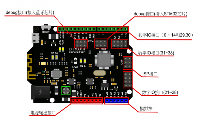
Bluno M3是非常容易使用通用输入/输出数字IO口,兼容Arduino的IO操作方式。但是拥有更多可操作的数字IO口,GPIO端口是从数字0到38。
GPIO 参考函数
I/O输入输出函数完全兼容Arduino uno控制方式。
函数接口:
pinMode(pin, mode);
digitalRead(pin);
digitalWrite(pin,value);
参考例程
int led = 13; // Pin 13 has an LED connected on most Arduino boards.
void setup() {
pinMode(led, OUTPUT); // initialize the digital pin as an output.
}
void loop() {
digitalWrite(led, HIGH); // turn the LED on (HIGH is the voltage level)
delay(1000); // wait for a second
digitalWrite(led, LOW); // turn the LED off by making the voltage LOW
delay(1000); // wait for a second
}
USART
概述
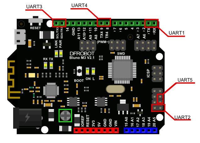
USART 是用来进行串口通信的,Bluno M3共有5个串口Serial1(TX1,RX1)、Serial2(TX2, RX2)、Serial3(TX3, RX3)、Serial4(TX4, RX4)、Serial5(TX5, RX5)。Bluno M3 的Uart与其他设备的Uart均采用交叉连接,即TX连接其他串口设备的RX,
它的RX连接其他设备的TX。Serial1与usb调试下载共用一个uart外设。
在使用的时候,假如用户想使用Uart1时,调用Serial函数即可,完全兼容Arduino函数库。
 USART 参考函数
支持Arduino基本串口库函数,参考Arduino官网:入口
参考例程
USART 参考函数
支持Arduino基本串口库函数,参考Arduino官网:入口
参考例程
/** *本例子实现了如下功能:
- 1、演示了Serial1-Serial5的初始化、读写流程。
/
void setup() {
/ initialize both serial ports.*/
Serial1.begin(9600);
Serial2.begin(9600);
Serial3.begin(9600);
Serial4.begin(9600);
Serial5.begin(9600);
Serial1.println("Bluno M3 Serials test begin .......!");
Serial1.println("Please choose the Serial to test,and Send a string for it:");
}
void loop() {
char arr[50];
int len;
char ch;
int i;
//Serial1.available()函数用于判断串口是否有可读数据并返回出当前可读的字节数。
if (Serial1.available()) {
    Serial1.println("the string you input just now is :");
    //读取出Serial1中的数据。
    ch = Serial1.read()
    //将数据回环输出
    Serial1.println(ch);
    Serial1.println("Please choose the Serial to test next,and Send a string for it:");
}
if ( Serial2.available()) {
    Serial2.println("the string you input just now is :");
    Serial2.println( ch = Serial2.read());
    Serial2.println("Please choose the Serial to test next,and Send a string for it:");
}
if (Serial3.available()) {
    Serial3.println("the string you input just now is :");
    Serial3.println( ch = Serial3.read());
    Serial3.println("Please choose the Serial to test next,and Send a string for it:");}
if (Serial4.available()) {
    Serial4.println("the string you input just now is :");
    Serial4.println( ch = Serial4.read());
    Serial4.println("Please choose the Serial to test next,and Send a string for it:");  }
if ( Serial5.available()) {
    Serial5.println("the string you input just now is :");
    Serial5.println( ch = Serial5.read());
    Serial5.println("Please choose the Serial to test next,and Send a string for it:"); }
}
PWM
概述
Bluno M3板子上标有“~”的端口都是PWM口(0, 1, 2, 3, 6, 7, 11, 12 , 21, 22,27, 28, 35, 36, 37, 38)。每个管脚都与内部的定时器各通道相连接,PWM模块已经把硬件封装好了,
在使用的过程中用户不需要关心内部定时器配置等情况。
Bluno M3支持两种方式对PWM模块进行操作:
方式一:
直接调用void analogWrite(uint32_t ulPin, uint32_t ulValue)该函数默认输出周期固定为1KHz、占空比由ulValue的值改变的PWM方波到ulPin指定的具有PWM功能的管脚,且PWM的分辨率为8位。这种方式限制了
PWM的输出能力。
方式二:
1、先调用void pwmMode( uint32_t ulPin, uint32_t pwmFre, uint32_t pwmMode)该函数配置指定输出PWM方波的管脚,pwm方波的频率和模式,其中模式有8位和12位之分,分别由PWM_8_BIT和PWM_12_BIT指定。
*在PWM_8_BIT模式下,pwmFre的取值范围为: 4Hz < pwmFre < 281250Hz.
*在PWM_12_BIT模式下,pwmFre的取值范围为: 1Hz < pwmFre < 17578Hz.
2、调用void pwmWrite(uint32_t ulPin, uint32_t ulValue)该函数给指定管脚ulPin输出一个值ulValue决定的占空比的PWM方波,占空比计算公式如下:
*在MODE_8_BIT下 ulValue 的取值范围是: 0 ~ 255, Dutycycle = ulValue / 255 * 100%
*在MODE_12_BIT下 ulValue 的取值范围是: 0 ~ 4095,Dutycycle = ulValue / 4095 * 100%
 PWM 参考函数
void analogWrite(uint32_t ulPin, uint32_t ulValue)
函数功能: 输出一个占空比由ulValue决定且频率为1KHz的PWM方波。
参数说明:
ulPin:具有PWM功能的端口编号。例如指定D7端口输出PWM波形,则ulPin 传入7即口;
ulValue: 比较输出值,它决定了该方波的占空比,计算公式: 占空比 = (ulValue / 255 )* 100%,传值为0~255;
返回值:无。
void pwmMode( uint32_t ulPin, uint32_t pwmFre, uint32_t pwmMode)
函数功能:配置PWM的波形出去端口,PWM的频率以及PWM的模式。
参数说明:
ulPin:具有PWM功能的端口编号。例如指定D7端口输出PWM波形,则ulPin 传入7即口;
pwmFre:PWM的频率,其传值范围有pwmMode决定;
pwmMode:指定该PWM的分辨率,其值为MODE_8_BIT或者MODE_12_BIT;
返回值:无。
参考例程
PWM 参考函数
void analogWrite(uint32_t ulPin, uint32_t ulValue)
函数功能: 输出一个占空比由ulValue决定且频率为1KHz的PWM方波。
参数说明:
ulPin:具有PWM功能的端口编号。例如指定D7端口输出PWM波形,则ulPin 传入7即口;
ulValue: 比较输出值,它决定了该方波的占空比,计算公式: 占空比 = (ulValue / 255 )* 100%,传值为0~255;
返回值:无。
void pwmMode( uint32_t ulPin, uint32_t pwmFre, uint32_t pwmMode)
函数功能:配置PWM的波形出去端口,PWM的频率以及PWM的模式。
参数说明:
ulPin:具有PWM功能的端口编号。例如指定D7端口输出PWM波形,则ulPin 传入7即口;
pwmFre:PWM的频率,其传值范围有pwmMode决定;
pwmMode:指定该PWM的分辨率,其值为MODE_8_BIT或者MODE_12_BIT;
返回值:无。
参考例程
第一种方式示例代码:
// pwm connected to digital pin 0
int pwmPin = 0;
void setup() {
//nothing happens in setup
}
void loop() {
// fade in from min to max in increments of 5 points:
for (int fadeValue = 0 ; fadeValue <= 255; fadeValue += 5) {
     // sets the value (range from 0 to 255):
    analogWrite(pwmPin, fadeValue);
     // wait for 30 milliseconds to see the dimming effect
    delay(30);
}

// fade out from max to min in increments of 5 points:
for (int fadeValue = 255 ; fadeValue >= 0; fadeValue -= 5) {
    // sets the value (range from 0 to 255):
    analogWrite(pwmPin, fadeValue);
    // wait for 30 milliseconds to see the dimming effect
    delay(30);
}
}
第二种方式示例代码:
#include <Arduino.h>
int pwmPin = 0; // PWM connected to digital pin 0
int flag = 1;
void setup() {
//initailizing the pwmPin, setting the period of PWM as 2000Hz and it's mode as 8'bit.
pwmMode(pwmPin, 2000, PWM_8_BIT);
}
void loop() {
 // output the duty of the PWM , one is 39% based on the formula privided above.
 pwmWrite(pwmPin, 100);
 while (1);
}
ADC
概述
ADC模块可以将输入的模拟信号转化成数字信号,电压区间是0-3.3V,Bluno M3上共有模拟端口11个分别为(A0,A1,A2,A3,A4,A5,A6,A7,A8,A9,A10)。Bluno M3有两种方式对ADC模块进行操作:
方式一:
直接调用analogRead(uint32_t ulPin),默认10位分辨率采样。单次不循环采样,要实现循环采样必须在应用程序中循环调用analogRead();使用方式与Uno类似。
方式二:
1、先调用函数void adcMode(uint32_t ulPin, uint8_t Mode)设置指定的adc管脚的工作模式。模式有三种:ADC_8_BIT,ADC_10_BIT,ADC_12_BIT。
*ADC_8_BIT:把adc转换的结果映射在0~255范围内。
*ADC_10_BIT:把adc转换的结果映射在0~1023范围内。
*ADC_12_BIT:把adc转换的结果映射在0~4096范围内。
2、调用函数uint32_t adcRead(uint32_t ulPin)该函数将ulPin指定的模拟输入脚中的电压值转换成与Mode指定的分辨率相对应的数值,然后将其返回。比如模拟电压1.5V在ADC_8_BIT模式下,转换后得到116,
而在ADC_10_BIT下为465,在ADC_12_BIT模式下为1861。
ADC 参考函数
uint32_t analogRead(uint32_t ulPin)
函数功能:返回ulPin指定的adc转换后的结果。
参数说明:
ulPin: 具有ADC功能的管脚即标有字母A的管脚。比如要读入A0管脚的模拟输入值那么传入A0或者0即可,A0是定义的宏。
返回值:adc的转换结果。
void adcMode(uint32_t ulPin, uint8_t Mode)
函数功能:设置ulPin指定的adc管脚的工作模式。
参数说明:
ulPin:具有ADC功能的管脚即标有字母A的管脚。比如要读入A0管脚的模拟输入值那么传入A0或者0即可,A0是定义的宏。
Mode:指定输出的数据格式。Mode可以为ADC_8_BIT,ADC_10_BIT,ADC_12_BIT。
返回值:无。
uint32_t adcRead(uint32_t ulPin)
函数功能:返回一个由Mode指定的分辨率的数据。
参数说明:
ulPin:与adcMode中的端口编号一致。
返回值:adc的转换结果。
第一种方式示例代码:
int sensorPin = 0; // select the input pin for the potentiometer
int sensorValue = 0; // variable to store the value coming from the sensor
void setup() {
Serial1.begin(9600);
}
void loop() {
sensorValue = analogRead(sensorPin);
Serial1.println((int)sensorValue);
delay(1000);
}
第二种方式示例代码:
int sensorPin = 0; // select the input pin for the potentiometer
int sensorValue = 0; // variable to store the value coming from the sensor
void setup() {
Serial1.begin(9600);
adcMode(sensorPin, ADC_12_BIT);
}
void loop() {
sensorValue = adcRead(sensorPin);
Serial1.println((int)sensorValue);
delay(1000);
}
External Interrupts
概述
外部中断能够用来检测端口电平的改变,当检测到电平变化时,则调用注册的回调函数,执行相应功能。0-38都可以作为外部中断管脚。
 参考函数
void attachInterrupt(uint32_t pin, void (*callback)(void), uint32_t mode)
函数功能:配置一个指定的管脚为外部中断,并为该中断注册一个回调函数。
参数说明:
pin:0 ~ 38引脚编号。
callback:回调函数。
mode: 可以指定为CHANGE, RISING, FALLING中的其中一种。其中CHANGE指的是上升沿下降沿均被触发,RISING指的是上升沿触发,FALLING指的是下降沿触发。
返回值:无。
参考例程
参考函数
void attachInterrupt(uint32_t pin, void (*callback)(void), uint32_t mode)
函数功能:配置一个指定的管脚为外部中断,并为该中断注册一个回调函数。
参数说明:
pin:0 ~ 38引脚编号。
callback:回调函数。
mode: 可以指定为CHANGE, RISING, FALLING中的其中一种。其中CHANGE指的是上升沿下降沿均被触发,RISING指的是上升沿触发,FALLING指的是下降沿触发。
返回值:无。
参考例程
//define the extern interrupt pin.
char intNumber = 2;
void setup() {
//init the Serial1.
Serial1.begin(9600);
//register the interrupt handler for the pin and specify the interrupt mode in CHANGE mode
attachInterrupt(intNumber, warning, CHANGE);
}
void loop() {
}
/define a function as the handler when the extern Interrupt assert/
void warning(){
Serial1.println((int)intNumber);
}
I2C
概述
I2C总线是由PHILIPS公司开发的两线式总线,是一种串行外设总线接口,用于连接微控制器及其外围设备,是微电子通信控制领域广泛采用的一种总线标准。它是同步通信的一种特殊形式,具有接口线少,控制方式简单,
器件封装形式小,通信速率较高等优点。I2C 总线支持任何IC 生产过程(CMOS、双极性)。通过串行数据(SDA)线和串行时钟(SCL)线在连接到总线的器件间传递信息。每个器件都有一个唯一的器件地址(无论是微控制器
——MCU、LCD 驱动器、存储器或键盘接口),而且都可以作为一个发送器或接收器(由器件的功能决定)。LCD 驱动器只能作为接收器,而存储器则既可以接收又可以发送数据。除了发送器和接收器外,器件在执行数据传输时
也可以被看作是主机或从机。主机是初始化总线并产生时钟信号的器件。此时,任何被寻址的器件都被认为是从机。Bluno M3提供两个硬件I2C端口,分别是I2C1和I2C2,但由于采用软件模拟I2C灵活高,易实现,仅需要任意
两个通用I0口即可,所以现在我们的板子只提供软件模拟的I2C接口,将来的版本可能会兼容硬件I2C。Bluno M3为了兼容UNO,直接用Wire操作就可以了。在调用 Wire.begin()时,默认配置了板子上的SDA,SCL这两个端口作为模拟I2C接口。
参考例程
/*
- 此代码实现了利用I2C总线对24C256 芯片的读写。
*/
#include <Wire.h> //I2C library
#define EEPROM_ADDR 0x50 // I2C Buss address of 24LC256 256K EEPROM
#define PAGESIZE 64 // 64 bytes each Page of 24LC256
int temp ;
void setup()
{
Wire.begin(); // join I2C bus (address optional for master)
Serial1.begin(9600);
}
void loop()
{
int i;
byte arr[64];
byte arread[64];
// TESTS FOR EACH FUNCTION BEGIN HERE
Serial1.println("the data is going to be write to the 24LC256:");
for (i = 0; i < PAGESIZE; i++)
{
arr[i] = i;
Serial1.print(i);
Serial1.print(' ');
if (i != 0 && i % 10 == 0)
Serial1.println("");
}
      Serial1.println("");
     i2c_eeprom_write_page(EEPROM_ADDR, 0, arr, PAGESIZE);
     delay(100);

     i2c_eeprom_read_buffer(EEPROM_ADDR, 0, arread,PAGESIZE);
     Serial1.println("the data is reading from the 24LC256  :");
     delay(1000);

     for (i = 0; i < PAGESIZE; i++)
     {
         Serial1.print(arread[i]);
         Serial1.print(' ');
         if (i != 0 &&i % 10 == 0)
             Serial1.println("");

     }
      Serial1.println("");
     if (memcmp(arr, arread, PAGESIZE) == 0)
     {
         Serial1.println("the driver of the 24LC256 correct!");
     }
     else
     {
          Serial1.println("the driver of the 24LC256 fault!");
     }

     while (1);
}
void i2c_eeprom_write_byte( int deviceaddress, unsigned int eeaddress, byte data ) {
int rdata = data;
Wire.beginTransmission(deviceaddress);
Wire.write((int)(eeaddress >> 8)); // MSB
Wire.write((int)(eeaddress & 0xFF)); // LSB
Wire.write(rdata);
Wire.endTransmission();
}
// WARNING: address is a page address, 6-bit end will wrap around
// also, data can be maximum of about 30 bytes, because the Wire library has a buffer of 32 bytes
void i2c_eeprom_write_page( int deviceaddress, unsigned int eeaddresspage, byte* data, byte length ) {
Wire.beginTransmission(deviceaddress);
Wire.write((int)(eeaddresspage >> 8)); // MSB
Wire.write((int)(eeaddresspage & 0xFF)); // LSB
byte c;
for ( c = 0; c < length; c++)
Wire.write(data[c]);
Wire.endTransmission();
}
byte i2c_eeprom_read_byte( int deviceaddress, unsigned int eeaddress ) {
byte rdata = 0xFF;
Wire.beginTransmission(deviceaddress);
Wire.write((int)(eeaddress >> 8)); // MSB
Wire.write((int)(eeaddress & 0xFF)); // LSB
Wire.endTransmission();
Wire.requestFrom(deviceaddress,1);
if (Wire.available()) rdata = Wire.read();
return rdata;
}
// maybe let's not read more than 30 or 32 bytes at a time!
void i2c_eeprom_read_buffer( int deviceaddress, unsigned int eeaddress, byte *buffer, int length ) {
Wire.beginTransmission(deviceaddress);
Wire.write((int)(eeaddress >> 8)); // MSB
Wire.write((int)(eeaddress & 0xFF)); // LSB
Wire.endTransmission();
Wire.requestFrom(deviceaddress,length);
int c = 0;
for ( c = 0; c < length; c++ )
if (Wire.available()) buffer[c] = Wire.read();
}
SPI
概述
SPI是一种高速、全双工和同步的通信总线。Bluno M3 提供两个SPI接口,分别是SPI和SPI1,这两个对象已经在库中定义好了,用户在编码时可以直接使用这两个对象对SPI总线进行操作。
/**
*代码演示了使用SPI对象中的方法去驱动SD卡。
*1、这是一份完整的sd卡驱动代码。
*2、应该重点关注SPI的用法。
*/
#include "SPI.h"
#define SD_TYPE_ERR 0X00
#define SD_TYPE_MMC 0X01
#define SD_TYPE_V1 0X02
#define SD_TYPE_V2 0X04
#define SD_TYPE_V2HC 0X06
#define CMD0 0
#define CMD1 1
#define CMD8 8
#define CMD9 9
#define CMD10 10
#define CMD12 12
#define CMD16 16
#define CMD17 17
#define CMD18 18
#define CMD23 23
#define CMD24 24
#define CMD25 25
#define CMD41 41
#define CMD55 55
#define CMD58 58
#define CMD59 59
#define MSD_DATA_OK 0x05
#define MSD_DATA_CRC_ERROR 0x0B
#define MSD_DATA_WRITE_ERROR 0x0D
#define MSD_DATA_OTHER_ERROR 0xFF
#define MSD_RESPONSE_NO_ERROR 0x00
#define MSD_IN_IDLE_STATE 0x01
#define MSD_ERASE_RESET 0x02
#define MSD_ILLEGAL_COMMAND 0x04
#define MSD_COM_CRC_ERROR 0x08
#define MSD_ERASE_SEQUENCE_ERROR 0x10
#define MSD_ADDRESS_ERROR 0x20
#define MSD_PARAMETER_ERROR 0x40
#define MSD_RESPONSE_FAILURE 0xFF
const int slaveSelectPin = 4;
u8 SD_Type=0;
u8 SD_WaitReady(void)
{
u32 t=0;
do
{
if(SPI.transfer(0xff)==0xff)
{
return 0;//is ok!!!
}
t++;
}while(t<0xffffff);
return 1;
}
void SD_DisSelect(void)
{
digitalWrite(slaveSelectPin, HIGH);
SPI.transfer(0xff);
}
u8 SD_Select(void)
{
digitalWrite(slaveSelectPin, LOW);
if(SD_WaitReady()==0)
return 0;
SD_DisSelect();
return 1;
}
u8 SD_SendCmd(u8 cmd, u32 arg, u8 crc)
{
u8 r1;
u8 Retry=0;
SD_DisSelect();
if(SD_Select())
{
return 0XFF;
}
SPI.transfer(cmd | 0x40);//·Ö±ðдÈëÃüÁî
SPI.transfer(arg >> 24);
SPI.transfer(arg >> 16);
SPI.transfer(arg >> 8);
SPI.transfer(arg);
SPI.transfer(crc);
if(cmd==CMD12)
SPI.transfer(0xff);
Retry=0X1F;
do
{
r1=SPI.transfer(0xFF);
}while((r1&0X80) && Retry--);
return r1;
}
u8 SD_Initialize(void)
{
u16 retry;
u8 r1;
u8 buf[4];
u16 i;
// set the slaveSelectPin as an output:
pinMode (slaveSelectPin, OUTPUT);
// initialize SPI:
SPI.begin();
SPI.setClockDivider(SPI_CLOCK_DIV256);
SPI.setDataMode(SPI_MODE3);
//SPI.setDataMode(SPI_MODE3);
SPI.setClockDivider(SPI_CLOCK_DIV256);
for(int i=0;i<10;i++)
SPI.transfer(0xff);
retry=20;
do
{
r1=SD_SendCmd(CMD0,0,0x95);
}while((r1!=0x01)&&retry--);
SD_Type=0;
if(r1==0X01)
{
if(SD_SendCmd(CMD8,0x1AA,0x87)==1)//SD V2.0
{
for(int i=0;i<4;i++)buf[i]=SPI.transfer(0XFF);
if(buf[2]==0X01&&buf[3]==0XAA)
{
retry=0XFFFE;
do
{
SD_SendCmd(CMD55,0,0X01);
r1=SD_SendCmd(CMD41,0x40000000,0X01);
}while(r1&&retry--);
if(retry&&SD_SendCmd(CMD58,0,0X01)==0)
{
for(int i=0;i<4;i++)buf[i]=SPI.transfer(0XFF);
if(buf[
u8 SD_GetResponse(u8 Response)
{
u16 Count=0xFFF;
while ((SPI.transfer(0XFF)!=Response)&&Count)Count--;
if (Count==0)return MSD_RESPONSE_FAILURE;
else return MSD_RESPONSE_NO_ERROR;
}
u8 SD_RecvData(u8*buf,u16 len)
{
if(SD_GetResponse(0xFE))return 1;
while(len--)
{
*buf=SPI.transfer(0xFF);
buf++;
}
SPI.transfer(0xFF);
SPI.transfer(0xFF);
return 0;
}
u8 SD_GetCSD(u8 *csd_data)
{
u8 r1;
r1=SD_SendCmd(CMD9,0,0x01);
if(r1==0)
{
r1=SD_RecvData(csd_data, 16);
}
SD_DisSelect();
if(r1)
return 1;
else
return 0;
}
u32 SD_GetSectorCount(void)
{
u8 csd[16];
u32 Capacity;
u8 n;
u16 csize;
if(SD_GetCSD(csd)!=0)
{
return 0;
}
if((csd[0]&0xC0)==0x40)
{
    csize = csd[9] + ((u16)csd[8] << 8) + 1;
    Capacity = (u32)csize << 10;
}
else
{
    n = (csd[5] & 15) + ((csd[10] & 128) >> 7) + ((csd[9] & 3) << 1) + 2;
    csize = (csd[8] >> 6) + ((u16)csd[7] << 2) + ((u16)(csd[6] & 3) << 10) + 1;
    Capacity= (u32)csize << (n - 9);
}
return Capacity;
}
u8 SD_ReadDisk(u8* buf,u32 sector,u8 cnt)
{
u8 r1;
if(SD_Type!=SD_TYPE_V2HC)sector <<= 9;
if(cnt==1)
{
r1=SD_SendCmd(CMD17,sector,0X01);
if(r1==0)
{
r1=SD_RecvData(buf,512);
}
}else
{
r1=SD_SendCmd(CMD18,sector,0X01);
do
{
r1=SD_RecvData(buf,512);
buf+=512;
}while(--cnt && r1==0);
SD_SendCmd(CMD12,0,0X01);
}
SD_DisSelect();
return r1;//
}
u8 SD_WriteDisk(u8* buf,u32 sector,u8 cnt)
{
u8 r1;
if(SD_Type!=SD_TYPE_V2HC)sector *= 512;
if(cnt==1)
{
r1=SD_SendCmd(CMD24,sector,0X01);
if(r1==0)
{
r1=SD_SendBlock(buf,0xFE);
}
}
else
{
if(SD_Type!=SD_TYPE_MMC)
{
SD_SendCmd(CMD55,0,0X01);
SD_SendCmd(CMD23,cnt,0X01);
}
r1=SD_SendCmd(CMD25,sector,0X01);
if(r1==0)
{
do
{
r1=SD_SendBlock(buf,0xFC);
buf+=512;
}while(--cnt && r1==0);
r1=SD_SendBlock(0,0xFD);
}
}
SD_DisSelect();
return r1;//
}
u8 SD_SendBlock(u8*buf,u8 cmd)
{
u16 t;
if(SD_WaitReady())return 1;
SPI.transfer(cmd);
if(cmd!=0XFD)
{
for(t=0;t<512;t++)
SPI.transfer(buf[t]);
SPI.transfer(0xFF);
SPI.transfer(0xFF);
t=SPI.transfer(0xFF);
if((t&0x1F)!=0x05)return 2;
}
return 0;
}
void setup()
{
u32 sector_size;
u8 ybuf[512]="DFROBOT!";
u8 xbuf[512];
Serial1.begin(9600);
// SPI.begin();
Serial1.println("Serial1 init is OK!");
while(SD_Initialize()!=0)
{
Serial1.println("SD init Failed");
delay(1000);
}
Serial1.println("SD init OK!");
sector_size=SD_GetSectorCount()/1024;
// sector_size=0x3af000;
Serial1.println(sector_size/4);
SD_WriteDisk(ybuf,0,1);
delay(500);
SD_ReadDisk(xbuf,0,1);
Serial1.println(xbuf[
void loop() {
// put your main code here, to run repeatedly:
}
Timer
概述
Bluno M3的软件库里实现了一个软件定时器,用于满足用户在某些特殊场合下的定时处理需求。该定时器被封装在Timer类中,用于只需要定义并初始化对象就可以方便使用。Timer支持单次定时模式和周期性定时模式,
同一个定时器对象可以在两种模式之间切换。Timer类也支持回掉函数的更换。
参考函数
Timer(void)
函数功能:默认构造函数。
参数说明:
无参数。
返回值: 无。
Timer(uint32_t ms, Func tfunc, tKind_t mode, void data)
函数功能:支持实例化对象时传参。
参数说明:
ms:定时时间,单位:ms;
tfunc:注册的回调函数,函数的类型为void (Func)(void *);
mode:指定该定时器的类型,mode可以是t_single或者t_period中的一种;t_single表示的是:该定时器定时时间一到调用完回调函数后就自动销毁了,即调用一次回调函数后就不能在用了;t_period表示:该定时器周期
性的被中断,回调函数周期性的被调用,用户可以手动的调用该定时器的析构函数将其销毁。
data:回调函数需要处理的数据指针;
返回值: 无。
~Timer():
函数功能:析构函数,调用后定时器自动销毁。
参数说明:
无参数。
返回值: 无。
void config(uint32_t ms, Func tfunc, tKind_t mode, void data)
函数说明:用于配置定时器对象的函数。
参数说明:
ms:定时时间,单位:ms;
tfunc:注册的回调函数,函数的类型为void (Func)(void *);
mode:指定该定时器的类型。mode可以是t_single或者t_period中的一种;
data:回调函数需要处理的数据指针;
返回值: 无。
uint8_t get_tNum(void)
函数说明:返回当前定时器的序列号。
参数说明:
无参数。
返回值:当前定时器的序列号。该序列号是创建定时器时分配的。
uint32_t get_resTime(void)
函数说明:返回当前定时器的剩余时间,单位ms。
参数说明:
无参数。
返回值: 定时器倒计时值,即剩余时间。
void change_callbackFunc(Func ttFunc)
函数说明:改变当前定时器的回调函数。
参数说明:
ttFunc:函数指针,或函数名。
返回值: 无。
void change_mode(tKind_t mode)
函数说明:改变当前定时器的模式。
参数说明:
mode: 可以是t_single或者t_period;
返回值: 无。
参考例程
/***
*此代码演示了如何使用Bluno M3内置的软件定时器。
*/
#include "timerobj.h"
#include <stdlib.h>
unsigned char td;
/define the objects of the Timer that are best to be a global variable/
//instantiate a object of the class Timer with the hook function myfunc,and speicify the mode t_period.
Timer timer1(1000, myfunc, t_period, NULL );
Timer timer2(3000, myfunc1, t_period, NULL );
void myfunc(void *data)
{
Serial1.println("it is processing the first call back function! on timer1\n");
}
void myfunc1(void *data)
{
static int i;
i++;
Serial1.println(i);
Serial1.println("it is processing the second call back function! on timer2\n");
 if (i == 3)
 {
     Serial1.println("changing the callback function for the timer1\n");
     timer1.change_callbackFunc(myfunc2);  // changing the callback function for the object timer1
  }
}
void myfunc2(void *data)
{
  static int i;
  i++;
  Serial1.println(i);
  Serial1.println("myfunc2");
  if (i == 2)
  {
     Serial1.println("changing the kind of modefor timer2\n");
     timer2.change_mode(t_single);  // changing the mode for the timer2 from t_period to t_single.
  }
}
void setup() {
Serial1.begin(9600);
}
void loop() {
}
Servo
概述
舵机是一种伺服电机,可以通过PWM波信号给定转角角度信息,转动致指定角度并能保持、承受一定的外力矩。Bluno M3的舵机用户使用接口与Uno是一致的。Bluno 中构造了Servo类,如果用户想使用一个舵机
那么就调用attach()函数并参入一个端口信息实例化一个对象,该对象可以调用servo类的接口函数去实现各种复杂的功能。一个舵机对用一个Servo对象,这样的封装使用户对舵机的操作更加变得容易,方便。
参考函数
uint8_t attach(int pin)
函数功能:把pin指定的端口用于驱动舵机,并返回该舵机在所有正在使用的舵机中的编号。
参数说明:
pin: 0~38中的任意一个端口号。
返回值:返回该舵机在所有正在使用的舵机中的编号。
void write(int value)
函数功能:给定舵机一个旋转的角度值。
参数说明:
value:指定舵机旋转的度数,例如:如果要使舵机旋转1度,那么就让value = 1;如果要使舵机旋转20°,那么就让value = 20即可。
返回值:无。
参考例程
/* Sweep
This example code is in the public domain.
*/
#include <ServoM3.h>
Servo myservo; // create servo object to control a servo
// twelve servo objects can be created on most boards
int pos = 0; // variable to store the servo position
void setup()
{
myservo.attach(9); // attaches the servo on pin 9 to the servo object
}
void loop()
{
for(pos = 0; pos <= 180; pos += 1) // goes from 0 degrees to 180 degrees
{ // in steps of 1 degree
myservo.write(pos); // tell servo to go to position in variable 'pos'
delay(15); // waits 15ms for the servo to reach the position
}
for(pos = 180; pos>=0; pos-=1) // goes from 180 degrees to 0 degrees
{
myservo.write(pos); // tell servo to go to position in variable 'pos'
delay(15); // waits 15ms for the servo to reach the position
}
}
Flash
概述
Bluno M3采用的是stm32f103的ARM处理器,内部自带了一个容量为512K的flash,在它上面可以存储并运行程序,也可以存储用户数据。flash共256个page,每个page大小为2KByte。一般地,在对flash写之前必须要先进行擦除
操作,一次最多只能写一个page大小。如果用户直接对flash底层进行操作的话,难度大,不容易实现,并且严重影响用户设计的嵌入式系统的稳定性。为此Bulno M3在软件库里实现一个专门的Flash类,该封装了stm32f103芯片
中的内部flash。它将flash分为两大区域:代码区和用户数据区。代码区是程序存储运行的地方,对用户来说是不可见的,地址范围0x00000000~0x0807B000;而用户数据区可以被用户擦除,读写等,地址范围:0x0807B000
~0x08080000;这样用户可以不需要外接存储芯片的情况下也有20K Flash空间可用于存储数据。Flash类使用起来非常方便,用户在写数据时可以不用考虑该区域flash是否已擦除。因为 Write函数自带擦除功能;用户也不需要
考虑flash换页问题,因为Write函数实现了自动换页功能,使存储的数据在flash内部分布紧凑,大大提高了flash的利用率。
参考函数
FLASH_Status ErasePage(uint32_t Page_Address)
函数功能:擦除一个page。
参数说明:
Page_Address: page的首地址。 计算公式:Page_Address = x0807B000 + i * 2048; i指的是page的编号,i = (0,1,2,...,19)。
返回值:如果擦除成功则返回FLASH_COMPLETE,即十进制4。FLASH_Status的定义如下: typedef enum{ FLASH_BUSY = 1,FLASH_ERROR_PG,FLASH_ERROR_WRP, FLASH_COMPLETE, FLASH_TIMEOUT } FLASH_Status;
FLASH_Status EraseAllPages(void)
函数功能:擦除整块用户数据区;当然代码区不会被擦除。
参数说明:
无参数。
返回值:如果擦除成功则返回FLASH_COMPLETE,即十进制4;
void Read(uint32_t Addr, void *data, uint32_t NumByteToRead)
函数功能:指定的起始地址进行多字节读。
参数说明:
Addr:读起始地址,有效地flash地址即Addr必须在0x0807B000~0x08080000之间;
data:存放读取数据的buffer;
NumByteToRead: 指定需要读出的字节个数;
返回值: 无。
uint16_t Read(uint32_t Addr)
函数功能:单字节读。
参数说明:
Addr:将读取数据所在的地址。
返回值:返回所读取的数据,16位的数据。
FLASH_Status Write(uint32_t WriteAddr, uint16_t data)
函数功能:写入一个16位数据。
参数说明:
WriteAddr:有效地flash地址即Addr必须在0x0807B000~0x08080000之间;
data:将要被写入的数据。
返回值:写入成功返回FLASH_COMPLETE;
void Write(uint32_t WriteAddr, void *data, uint32_t NumByteToWrite)
函数功能:对指定的起始地址进行多字节写;
参数说明:
WriteAddr:写起始地址,有效地flash地址即Addr必须在0x0807B000~0x08080000之间;
data,将要被写入的数据缓存去的地址;
NumByteToWrite:指定将要写入的字节数。
返回值: 无。
uint32_t GetFlashSpace(void)
函数功能:返回用户数据区的空间大小。
参数说明:
无参数。
返回值:返回用户数据区的空间大小,单位:字节。
参考例程
#include <Flash.h>
void setup() {
// initialize the Serial1
Serial1.begin(9600);
}
void loop() {
unsigned short temp = 68, readBuf;

Serial1.println("the data to write is :");
Serial1.println(temp);
//write the value 68 to the address 0x0807B010 in flash.
flash.Write(0x0807B010, &temp, 1);
delay(1000);

Serial1.println("the data from reading is :");
//read the value to the variable for the address 0x0807B010 in flash
flash.Read(0x0807B010, &readBuf, 1);
Serial1.println(readBuf);

delay(10000);
}
Ethernet
概述
Bluno M3 完美兼容W5200网络扩展板。W5200嵌入式开发用的TCP/IP以太网接口模块,使用SPI接口。W5200适合用户构建TCP/IP协议栈或是针对10/100的以太网开发。W5200支持标准以太网,支持几乎所有TCP/IP协议栈
(包括TCP、UDP、IPV4、ICMP、ARP、IGMP和PPPoE)。W5200使用32KB内部通信缓冲。W5200模块可以让用户只需要使用简单的套接字程序,而不用考虑复杂的以太网编程。此模块通过LED直接显示网络速度模式(10Mb
或者100Mb)。Bluno M3的网络模块使用方式与Uno类似。
参考函数
Arduino官网Ethernet library接口函数使用说明入口:http://www.arduino.cc/en/Reference/Ethernet
参考例程
/* Web Server (based on the sheld W5200)
A simple web server that shows the value of the analog input pins.
using an Arduino Wiznet Ethernet shield.
Analog inputs attached to pins A0 through A5 (optional)
*/
#include <SPI.h>
#include <Ethernet.h>
//注意!官网的SPI接口使用的是 D10作为 SS接口,这里需要根据实际SS接线情况定义一次SS管脚
//the default ss pin is attached to 10 pin for the sheld W5200
#define SS 10
#define nRST 8
#define nPWDN 9
#define nINT 3
// Enter a MAC address and IP address for your controller below.
// The IP address will be dependent on your local network:
byte mac[] = {
0xDE, 0xAD, 0xBE, 0xEF, 0xFE, 0xED };
IPAddress ip(192,168,1,177);
// Initialize the Ethernet server library
// with the IP address and port you want to use
// (port 80 is default for HTTP):
EthernetServer server(80);
void setup() {
////下面是非常重要的设置,如果没有可靠的复位设置,W5200可能不工作 !!!! /////////
pinMode(SS,OUTPUT);
pinMode(nRST,OUTPUT);
pinMode(nPWDN,OUTPUT);
pinMode(nINT,INPUT);
digitalWrite(nPWDN,LOW); //enable power
digitalWrite(nRST,LOW); //Reset W5200
delay(10);
digitalWrite(nRST,HIGH);
delay(200); // wait W5200 work
/////////////////////////////////////////////////////////////
// Open Serial1 communications and wait for port to open:
Serial1.begin(9600);
while (!Serial1) {
; // wait for Serial1 port to connect. Needed for Leonardo only
}
// start the Ethernet connection and the server:
Ethernet.begin(mac, ip);
server.begin();
Serial1.print("server is at ");
Serial1.println(Ethernet.localIP());
}
void loop() {
// listen for incoming clients
EthernetClient client = server.available();
if (client) {
Serial1.println("new client");
// an http request ends with a blank line
boolean currentLineIsBlank = true;
while (client.connected()) {
if (client.available()) {
char c = client.read();
Serial1.write(c);
// if you've gotten to the end of the line (received a newline
// character) and the line is blank, the http request has ended,
// so you can send a reply
if (c == '\n' && currentLineIsBlank) {
// send a standard http response header
client.println("HTTP/1.1 200 OK");
client.println("Content-Type: text/html");
client.println("Connnection: close");
client.println();
client.println("<!DOCTYPE HTML>");
client.println("<html>");
// add a meta refresh tag, so the browser pulls again every 5 seconds:
client.println("<meta http-equiv="refresh" content="5">");
// output the value of each analog input pin
for (int analogChannel = 0; analogChannel < 6; analogChannel++) {
int sensorReading = analogRead(analogChannel);
client.print("analog input ");
client.print(analogChannel);
client.print(" is ");
client.print(sensorReading);
client.println("<br />");
}
client.println("</html>");
break;
}
if (c == '\n') {
// you're starting a new line
currentLineIsBlank = true;
}
else if (c != '\r') {
// you've gotten a character on the current line
currentLineIsBlank = false;
}
}
}
// give the web browser time to receive the data
delay(1);
// close the connection:
client.stop();
Serial1.println("client disonnected");
}
}
SD
概述
Bluno M3完美支持SD卡文件系统访问。其上层接口与Uno等类似。
参考函数
Arduino官网SD library函数接口入口:http://www.arduino.cc/en/Reference/SD
参考例程
/* SD card basic file example
This example shows how to create and destroy an SD card file
The circuit:
- SD card attached to SPI bus as follows:
** MOSI - pin 11
** MISO - pin 12
** CLK - pin 13
** CS - pin 4
This example code is in the public domain.
*/
#include <SPI.h>
#include <SD.h>
File myFile;
int cs_pin = 4; //D4 is attached as cs pin
void setup()
{
// Open serial communications and wait for port to open:
Serial1.begin(9600);
while (!Serial1) {
; // wait for serial port to connect. Needed for Leonardo only
}
Serial1.print("Initializing SD card...");
if (!SD.begin(cs_pin)) {
Serial1.println("initialization failed!");
return;
}
Serial1.println("initialization done.");
if (SD.exists("example.txt")) {
Serial1.println("example.txt exists.");
}
else {
Serial1.println("example.txt doesn't exist.");
}
// open a new file and immediately close it:
Serial1.println("Creating example.txt...");
myFile = SD.open("example.txt", FILE_WRITE);
myFile.close();
// Check to see if the file exists:
if (SD.exists("example.txt")) {
Serial1.println("example.txt exists.");
}
else {
Serial1.println("example.txt doesn't exist.");
}
// delete the file:
Serial1.println("Removing example.txt...");
SD.remove("example.txt");
if (SD.exists("example.txt")) {
Serial1.println("example.txt exists.");
}
else {
Serial1.println("example.txt doesn't exist.");
}
}
void loop()
{
// nothing happens after setup finishes.
}
Generate a Sine-wave by TIM8
概述
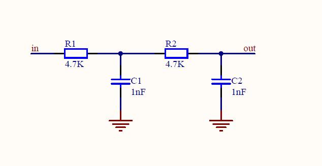
the application is useful for generator a sine-wave by TIM8,the frequence of which can be inditated form 70Hz to 2000Hz. In this application , only the out compare 1 chanel of TIM8
has initialized ,which generate a sine-wave on the PC8.Of course the PC8 must be attached a low pass filter,which can be made samply of two resistances and two capacitances,i.e.
RC integrated circuit.Generally TIM8 have 4 independent channels which can be configure as out compare mode, so user can change the following code to generate mulititude sine-wave at
the same time. the schematic drawing shows as follow:
应用程序代码
#define FAST_MATH_TABLE_SIZE 512
const float sinTable_f32[FAST_MATH_TABLE_SIZE + 1] = {
0.00000000f, 0.01227154f, 0.02454123f, 0.03680722f, 0.04906767f, 0.06132074f,
0.07356456f, 0.08579731f, 0.09801714f, 0.11022221f, 0.12241068f, 0.13458071f,
0.14673047f, 0.15885814f, 0.17096189f, 0.18303989f, 0.19509032f, 0.20711138f,
0.21910124f, 0.23105811f, 0.24298018f, 0.25486566f, 0.26671276f, 0.27851969f,
0.29028468f, 0.30200595f, 0.31368174f, 0.32531029f, 0.33688985f, 0.34841868f,
0.35989504f, 0.37131719f, 0.38268343f, 0.39399204f, 0.40524131f, 0.41642956f,
0.42755509f, 0.43861624f, 0.44961133f, 0.46053871f, 0.47139674f, 0.48218377f,
0.49289819f, 0.50353838f, 0.51410274f, 0.52458968f, 0.53499762f, 0.54532499f,
0.55557023f, 0.56573181f, 0.57580819f, 0.58579786f, 0.59569930f, 0.60551104f,
0.61523159f, 0.62485949f, 0.63439328f, 0.64383154f, 0.65317284f, 0.66241578f,
0.67155895f, 0.68060100f, 0.68954054f, 0.69837625f, 0.70710678f, 0.71573083f,
0.72424708f, 0.73265427f, 0.74095113f, 0.74913639f, 0.75720885f, 0.76516727f,
0.77301045f, 0.78073723f, 0.78834643f, 0.79583690f, 0.80320753f, 0.81045720f,
0.81758481f, 0.82458930f, 0.83146961f, 0.83822471f, 0.84485357f, 0.85135519f,
0.85772861f, 0.86397286f, 0.87008699f, 0.87607009f, 0.88192126f, 0.88763962f,
0.89322430f, 0.89867447f, 0.90398929f, 0.90916798f, 0.91420976f, 0.91911385f,
0.92387953f, 0.92850608f, 0.93299280f, 0.93733901f, 0.94154407f, 0.94560733f,
0.94952818f, 0.95330604f, 0.95694034f, 0.96043052f, 0.96377607f, 0.96697647f,
0.97003125f, 0.97293995f, 0.97570213f, 0.97831737f, 0.98078528f, 0.98310549f,
0.98527764f, 0.98730142f, 0.98917651f, 0.99090264f, 0.99247953f, 0.99390697f,
0.99518473f, 0.99631261f, 0.99729046f, 0.99811811f, 0.99879546f, 0.99932238f,
0.99969882f, 0.99992470f, 1.00000000f, 0.99992470f, 0.99969882f, 0.99932238f,
0.99879546f, 0.99811811f, 0.99729046f, 0.99631261f, 0.99518473f, 0.99390697f,
0.99247953f, 0.99090264f, 0.98917651f, 0.98730142f, 0.98527764f, 0.98310549f,
0.98078528f, 0.97831737f, 0.97570213f, 0.97293995f, 0.97003125f, 0.96697647f,
0.96377607f, 0.96043052f, 0.95694034f, 0.95330604f, 0.94952818f, 0.94560733f,
0.94154407f, 0.93733901f, 0.93299280f, 0.92850608f, 0.92387953f, 0.91911385f,
0.91420976f, 0.90916798f, 0.90398929f, 0.89867447f, 0.89322430f, 0.88763962f,
0.88192126f, 0.87607009f, 0.87008699f, 0.86397286f, 0.85772861f, 0.85135519f,
0.84485357f, 0.83822471f, 0.83146961f, 0.82458930f, 0.81758481f, 0.81045720f,
0.80320753f, 0.79583690f, 0.78834643f, 0.78073723f, 0.77301045f, 0.76516727f,
0.75720885f, 0.74913639f, 0.74095113f, 0.73265427f, 0.72424708f, 0.71573083f,
0.70710678f, 0.69837625f, 0.68954054f, 0.68060100f, 0.67155895f, 0.66241578f,
0.65317284f, 0.64383154f, 0.63439328f, 0.62485949f, 0.61523159f, 0.60551104f,
0.59569930f, 0.58579786f, 0.57580819f, 0.56573181f, 0.55557023f, 0.54532499f,
0.53499762f, 0.52458968f, 0.51410274f, 0.50353838f, 0.49289819f, 0.48218377f,
0.47139674f, 0.46053871f, 0.44961133f, 0.43861624f, 0.42755509f, 0.41642956f,
0.40524131f, 0.39399204f, 0.38268343f, 0.37131719f, 0.35989504f, 0.34841868f,
0.33688985f, 0.32531029f, 0.31368174f, 0.30200595f, 0.29028468f, 0.27851969f,
0.26671276f, 0.25486566f, 0.24298018f, 0.23105811f, 0.21910124f, 0.20711138f,
0.19509032f, 0.18303989f, 0.17096189f, 0.15885814f, 0.14673047f, 0.13458071f,
0.12241068f, 0.11022221f, 0.09801714f, 0.08579731f, 0.07356456f, 0.06132074f,
0.04906767f, 0.03680722f, 0.02454123f, 0.01227154f, 0.00000000f, -0.01227154f,
-0.02454123f, -0.03680722f, -0.04906767f, -0.06132074f, -0.07356456f,
-0.08579731f, -0.09801714f, -0.11022221f, -0.12241068f, -0.13458071f,
-0.14673047f, -0.15885814f, -0.17096189f, -0.18303989f, -0.19509032f,
-0.20711138f, -0.21910124f, -0.23105811f, -0.24298018f, -0.25486566f,
-0.26671276f, -0.27851969f, -0.29028468f, -0.30200595f, -0.31368174f,
-0.32531029f, -0.33688985f, -0.34841868f, -0.35989504f, -0.37131719f,
-0.38268343f, -0.39399204f, -0.40524131f, -0.41642956f, -0.42755509f,
-0.43861624f, -0.44961133f, -0.46053871f, -0.47139674f, -0.48218377f,
-0.49289819f, -0.50353838f, -0.51410274f, -0.52458968f, -0.53499762f,
-0.54532499f, -0.55557023f, -0.56573181f, -0.57580819f, -0.58579786f,
-0.59569930f, -0.60551104f, -0.61523159f, -0.62485949f, -0.63439328f,
-0.64383154f, -0.65317284f, -0.66241578f, -0.67155895f, -0.68060100f,
-0.68954054f, -0.69837625f, -0.70710678f, -0.71573083f, -0.72424708f,
-0.73265427f, -0.74095113f, -0.74913639f, -0.75720885f, -0.76516727f,
-0.77301045f, -0.78073723f, -0.78834643f, -0.79583690f, -0.80320753f,
-0.81045720f, -0.81758481f, -0.82458930f, -0.83146961f, -0.83822471f,
-0.84485357f, -0.85135519f, -0.85772861f, -0.86397286f, -0.87008699f,
-0.87607009f, -0.88192126f, -0.88763962f, -0.89322430f, -0.89867447f,
-0.90398929f, -0.90916798f, -0.91420976f, -0.91911385f, -0.92387953f,
-0.92850608f, -0.93299280f, -0.93733901f, -0.94154407f, -0.94560733f,
-0.94952818f, -0.95330604f, -0.95694034f, -0.96043052f, -0.96377607f,
-0.96697647f, -0.97003125f, -0.97293995f, -0.97570213f, -0.97831737f,
-0.98078528f, -0.98310549f, -0.98527764f, -0.98730142f, -0.98917651f,
-0.99090264f, -0.99247953f, -0.99390697f, -0.99518473f, -0.99631261f,
-0.99729046f, -0.99811811f, -0.99879546f, -0.99932238f, -0.99969882f,
-0.99992470f, -1.00000000f, -0.99992470f, -0.99969882f, -0.99932238f,
-0.99879546f, -0.99811811f, -0.99729046f, -0.99631261f, -0.99518473f,
-0.99390697f, -0.99247953f, -0.99090264f, -0.98917651f, -0.98730142f,
-0.98527764f, -0.98310549f, -0.98078528f, -0.97831737f, -0.97570213f,
-0.97293995f, -0.97003125f, -0.96697647f, -0.96377607f, -0.96043052f,
-0.95694034f, -0.95330604f, -0.94952818f, -0.94560733f, -0.94154407f,
-0.93733901f, -0.93299280f, -0.92850608f, -0.92387953f, -0.91911385f,
-0.91420976f, -0.90916798f, -0.90398929f, -0.89867447f, -0.89322430f,
-0.88763962f, -0.88192126f, -0.87607009f, -0.87008699f, -0.86397286f,
-0.85772861f, -0.85135519f, -0.84485357f, -0.83822471f, -0.83146961f,
-0.82458930f, -0.81758481f, -0.81045720f, -0.80320753f, -0.79583690f,
-0.78834643f, -0.78073723f, -0.77301045f, -0.76516727f, -0.75720885f,
-0.74913639f, -0.74095113f, -0.73265427f, -0.72424708f, -0.71573083f,
-0.70710678f, -0.69837625f, -0.68954054f, -0.68060100f, -0.67155895f,
-0.66241578f, -0.65317284f, -0.64383154f, -0.63439328f, -0.62485949f,
-0.61523159f, -0.60551104f, -0.59569930f, -0.58579786f, -0.57580819f,
-0.56573181f, -0.55557023f, -0.54532499f, -0.53499762f, -0.52458968f,
-0.51410274f, -0.50353838f, -0.49289819f, -0.48218377f, -0.47139674f,
-0.46053871f, -0.44961133f, -0.43861624f, -0.42755509f, -0.41642956f,
-0.40524131f, -0.39399204f, -0.38268343f, -0.37131719f, -0.35989504f,
-0.34841868f, -0.33688985f, -0.32531029f, -0.31368174f, -0.30200595f,
-0.29028468f, -0.27851969f, -0.26671276f, -0.25486566f, -0.24298018f,
-0.23105811f, -0.21910124f, -0.20711138f, -0.19509032f, -0.18303989f,
-0.17096189f, -0.15885814f, -0.14673047f, -0.13458071f, -0.12241068f,
-0.11022221f, -0.09801714f, -0.08579731f, -0.07356456f, -0.06132074f,
-0.04906767f, -0.03680722f, -0.02454123f, -0.01227154f, -0.00000000f
};
/*Tim8 ccr address */
#define TIM8_CCR1_Address 0x40013434
#define TIM8_CCR2_Address 0x40013438
#define TIM8_CCR3_Address 0x4001343C
#define TIM8_CCR4_Address 0x40013440
static uint16_t Ctcs_Table[4500];
void RCC_Configuration(void)
{
/* TIM8 and GPIOC clock enable /
RCC_APB2PeriphClockCmd(RCC_APB2Periph_TIM8 | RCC_APB2Periph_GPIOC
, ENABLE);
/ DMA 2 clock enable */
RCC_AHBPeriphClockCmd(RCC_AHBPeriph_DMA2, ENABLE);
}
void GPIO_Configuration(void)
{
GPIO_InitTypeDef GPIO_InitStructure;
/* GPIOC Configure: Channel 1 as alternate function push-pull */
GPIO_InitStructure.GPIO_Pin =  GPIO_Pin_6;
GPIO_InitStructure.GPIO_Mode = GPIO_Mode_AF_PP;
GPIO_InitStructure.GPIO_Speed = GPIO_Speed_50MHz;
GPIO_Init(GPIOC, &GPIO_InitStructure);
}
void DMA_Configuration(void)
{
DMA_InitTypeDef DMA_InitStructure;
/* DMA2 Channel3 Config */
DMA_DeInit(DMA2_Channel3);

DMA_InitStructure.DMA_PeripheralBaseAddr = (uint32_t)TIM8_CCR1_Address;
DMA_InitStructure.DMA_MemoryBaseAddr = (uint32_t)Ctcs_Table;
DMA_InitStructure.DMA_DIR = DMA_DIR_PeripheralDST;
DMA_InitStructure.DMA_PeripheralInc = DMA_PeripheralInc_Disable;
DMA_InitStructure.DMA_MemoryInc = DMA_MemoryInc_Enable;
DMA_InitStructure.DMA_PeripheralDataSize = DMA_PeripheralDataSize_HalfWord;
DMA_InitStructure.DMA_MemoryDataSize = DMA_MemoryDataSize_HalfWord;
DMA_InitStructure.DMA_Mode = DMA_Mode_Circular;
DMA_InitStructure.DMA_Priority = DMA_Priority_High;
DMA_InitStructure.DMA_M2M = DMA_M2M_Disable;

DMA_Init(DMA2_Channel3, &DMA_InitStructure);
}
float arm_sin_f32(float x)
{
float sinVal, fract, in;
uint16_t index;
float a, b;
int32_t n;
float findex;
in = x * 0.159154943092f;
n = (int32_t) in;
if(x < 0.0f)
{
n--;
}
in = in - (float) n;
findex = (float) FAST_MATH_TABLE_SIZE * in;
index = ((uint16_t)findex) & 0x1ff;
fract = findex - (float) index;
a = sinTable_f32[index];
b = sinTable_f32[index+1];

sinVal = (1.0f-fract)*a + fract*b;

return (sinVal);
}
#define SAMPLE_FREQ 282352 // the sample frequence of the pwm that is to be filtered by the attached low pass filter.
void DF_TIM8PwmInit(void)
{
TIM_TimeBaseInitTypeDef TIM_TimeBaseStructure;
TIM_OCInitTypeDef TIM_OCInitStructure;
NVIC_InitTypeDef NVIC_InitStructure;
DMA_InitTypeDef DMA_InitStructure;
RCC_Configuration();  //configure the RCC clock of related modules i.e. GPIOC,TIM8 etc.
GPIO_Configuration();  //configure the GPIO pin for TIM8 as alternate function.
DMA_Configuration();   //configure DMA channel for TIM8 the indicated out compare channel.
TIM_TimeBaseStructure.TIM_Period = 255; //set the sine wave

/*the source lock of TIM8 is 72MHz */
TIM_TimeBaseStructure.TIM_Prescaler = 1 - 1; // set the prescaler of TIM8 as 0,so the input clock of TIM8 is 72MHz.
TIM_TimeBaseStructure.TIM_ClockDivision = TIM_CKD_DIV1;
TIM_TimeBaseStructure.TIM_CounterMode = TIM_CounterMode_Up; // the counter mode is configured as upcounting mode
TIM_TimeBaseStructure.TIM_RepetitionCounter = 0x0;
TIM_TimeBaseInit(TIM8,&TIM_TimeBaseStructure);


/*configure the TIM8 as PWM1 Mode.*/
TIM_OCInitStructure.TIM_OCMode = TIM_OCMode_PWM1;
TIM_OCInitStructure.TIM_OutputState = TIM_OutputState_Enable;
TIM_OCInitStructure.TIM_OutputNState = TIM_OutputNState_Enable;
TIM_OCInitStructure.TIM_OCPolarity = TIM_OCPolarity_High;
TIM_OCInitStructure.TIM_OCIdleState = TIM_OCIdleState_Set;
TIM_OCInitStructure.TIM_OCNIdleState = TIM_OCNIdleState_Reset;
TIM_OCInitStructure.TIM_Pulse = 0;        // this parameter is very important,since the sine wave generating depends on changing the Pulse value which will be assined to CCRx.
                                          // of course the example is based on the DMA way, with the value of the CCRx register is updated by  TIM8_CCR1_Address,so user can ignore the variable.
TIM_OC1Init(TIM8, &TIM_OCInitStructure);  // initailize TIM8 out compare chanel
TIM_DMACmd(TIM8, TIM_DMA_CC1, ENABLE);    // enable the TIM8's out compare 1 chanle addressed by DMA.
}
const float pi = 3.1415;
/*calculate the a table depending on the Freq ,whose elements are used to update TIM8_CCR1_Address's value */
void DF_SinFreqSet(uint32_t Freq)
{
float fraction;
uint16_t i,a;
uint16_t Sample_Num;
/*calculate the number of the sample point*/
Sample_Num = SAMPLE_FREQ / Freq;
for (i = 0; i < Sample_Num; i++)
{
  /*use the formula to calculate the value corresponding to each point  */
  Ctcs_Table[i] = 127 * arm_sin_f32( 2 * pi * i / Sample_Num) + 128;

}

/*tell the DMA controller the total number of the data is to be transmit */
DMA2_Channel3->CNDTR = Sample_Num;
}
/start the sinewave generating./
void DF_SinStart(void)
{
/* DMA enable/
DMA_Cmd(DMA2_Channel3, ENABLE);
/enable the PWM out compare of TIM8/
TIM_CtrlPWMOutputs(TIM8,ENABLE);
/enable the TIM8 module*/
TIM_Cmd(TIM8,ENABLE);
}
/stop the sinewave generating/
void DF_SinStop(void)
{
/* DMA disable/
DMA_Cmd(DMA2_Channel3, DISABLE);
/disable the PWM out compare of TIM8/
TIM_CtrlPWMOutputs(TIM8, DISABLE);
/disable the TIM8 module*/
TIM_Cmd(TIM8, DISABLE);
}
void setup()
{
/initialize the TIM8 mode and DNMA etc. /
DF_TIM8PwmInit();
/set the sine-wave frequence as 1000Hz/
DF_SinFreqSet(1000);
/start the sine-wave generating/
DF_SinStart();
}
void loop() {
delay(10000);
/*expire the sine-wave Generating*/
DF_SinStop();
delay(10000);
/*change the sine-wave frequence as 2KHz*/
DF_SinFreqSet(2000);
/*start the sine-wave generating*/
DF_SinStart();
}
SWD
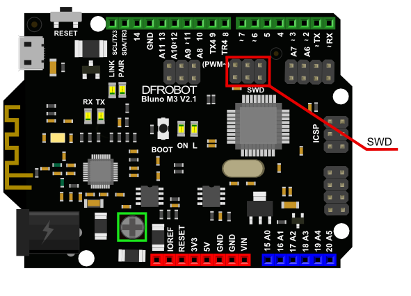
STM32F103RET6 支持SWD在线仿真调试,只需要4个PIN:GND、RST、SWDIO、SWDCLK,而且下载速度可以达到10M/s,Bluno M3提供了SWD端口用于STM32标准开发。SWD功能可以方便用户对stm32芯片内部的寄存器进行在线参看,试试监控芯片运行程序的状态等。
要使用SWD功能,首先要有仿真器,目前支持SWD的仿真器有ST-link 和J-Link,与之配套的IDE有IAR,Keil4等。我们的arduino开发环境不支持SWD在线调试,因此想用此功能则可以用IAR。关于IAR下面配置J-link的SWD功能的使用说明可以很容易在网上找到
相关教程,这里有一个写得比较好的教程可以参考:J-link调试STM32