海盗船基础套件
目录
1 功能介绍
2 组装步骤
2.1 安装电机
2.2 焊接电机线
2.3 安装Romeo BLE 控制器
2.4 安装电池盒
2.5 制作电源开关
2.6 组装底盘
2.7 连接电机
2.8 安装上层板
3 STEP2:调试电机
4 STEP3:安装上层板
5 STEP4: 调试超声波和舵机
6 STEP5: 整机调试
功能介绍
以海盗船为平台,用超声波作为距离检测装置,舵机作为前方扫描器,实现一个可自动蔽障小车。
组装步骤
工具准备就绪后,我们就要开始开工了!海盗船的底盘组装非常容易,只需要按照以下步骤一步步安装就行了。
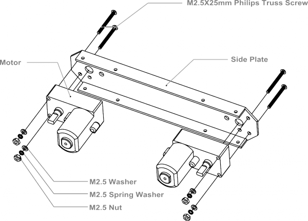
安装电机
拿出零件包,有找到8个长螺丝吗?那就是用来固定电机的。按下图位置摆放电机,找到对应的8个固定孔,拧上螺丝就行了。
这里可能需要注意的一点是,零件包里面还有配有垫圈和锁紧垫片。垫圈可以用于增加摩擦力,是电机固定更牢固。锁紧片用来防止螺母由于震动可能导致的松脱。
![]()

![]()
焊接电机线
取出套件里自带的红黑导线,每个电机红、黑各一根,长度大约在15cm左右。用剥线钳在线两头剥去外皮,留下导线用于焊接在电机引脚上。将四个电机线全部焊好。
注意:焊接的时候,注意线序正确,可参照下图的红黑线的位置。
        <img alt="Assemble Mobile Platform STEP2 1.png" src="http://images.ncnynl.com/arduino/2016/354px-Assemble_Mobile_Platform_STEP2_1.png" width="354" height="250" />


        <img alt="Assemble Mobile Platform STEP2 2.jpg" src="http://images.ncnynl.com/arduino/2016/316px-Assemble_Mobile_Platform_STEP2_2.jpg" width="316" height="250" />


        <img alt="Assemble Mobile Platform STEP2 3.png" src="http://images.ncnynl.com/arduino/2016/316px-Assemble_Mobile_Platform_STEP2_3.png" width="316" height="250" />
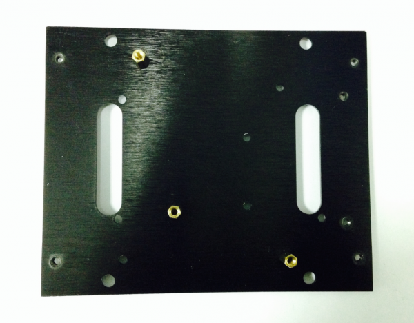
安装Romeo BLE 控制器
找到零件包中的3个1cm长的铜柱,那是用于固定控制板的。首先,需要找到控制器的三个固定空位。并将铜柱拧上去。完成之后,再将控制器用螺丝固定上去。
![]()

![]()
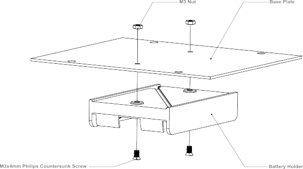
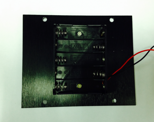
安装电池盒
取出独立包装的两个沉头(顶部是平的)螺丝,按下图装配图,将电池盒固定到底盘上。
![]()
![]()
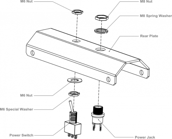
制作电源开关
我们都知道需要用电池来给机器人供电。平时不用的时候,需要断电来节约电量,那电源开关在这里就起到作用了。先按装配图将机器人的开关位置安装好。安装的时候注意垫片和螺母的顺序。
![]()
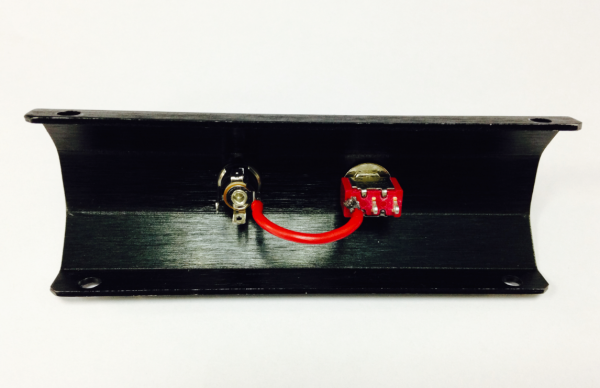
固定完成之后,就要开始焊线了,取出前面焊接电机连接线剩余的部分,可用于开关。同样,用剥线钳剥去线两头的外皮,留出导线部分用于焊接到开关的引脚上。焊接的时候注意看清楚开关的引脚位置。
![]()
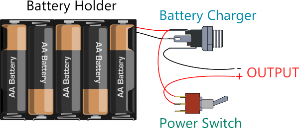
我们一步步来:
a) 连接开关和充电接头。注意找准位置。
![]()
b) 按上图连线图,将电池盒的两根线焊接到充电接头上。
![]()
来张大图,看的清楚点!

![]()
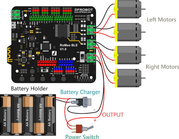
c) 最后,从充电接头和开关上引出正负极电源,用于接到后面的Romeo BLE主控器上。

![]()

![]()
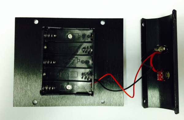
同样来张放大图,清楚是怎么连接的吗?最后,检查一下焊接的线是否和一开始的连线图是吻合的。
组装底盘
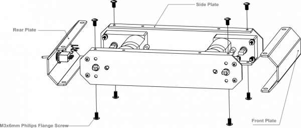
用8个M3×6mm的螺丝将前后板固定到侧板上。按下图装配图安装。
注意:拧螺丝的时候,不要一开始就将螺丝全拧紧,导致下一步安装上层板的时候。螺丝孔对应不上。
![]()
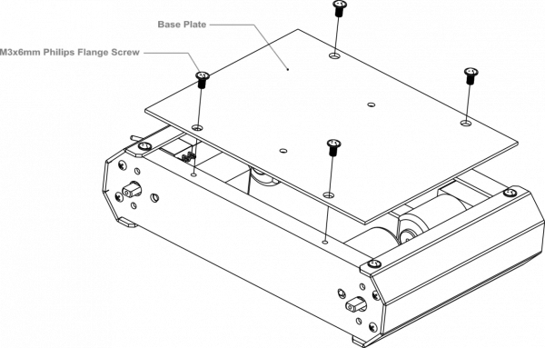
安装完后,将底板固定上去,见装配图。
![]()

![]()
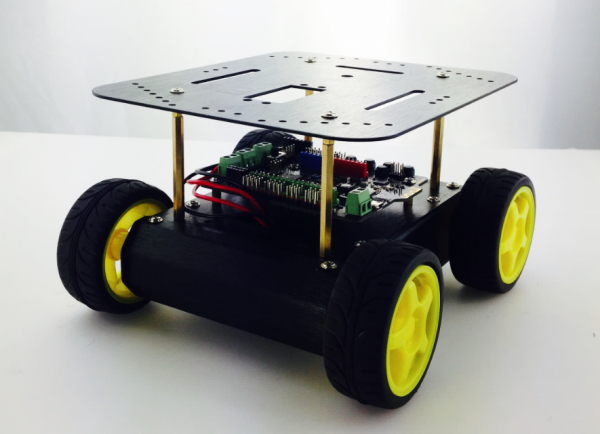
完成后的样子,记得装上电池!
连接电机
这一步我们需要将电机和我们的控制器连接起来,按下图连线图将电机线一一接到电机驱动的接线柱上,并用螺丝刀拧紧固定。
注意:同一侧的两个电机需要固定在同一个电机驱动接口上。
![]()

![]()
安装完成后,如下图所示。

![]()
安装上层板
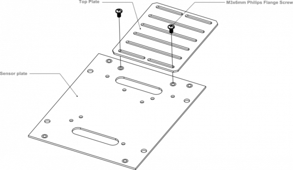
找到上层板的四个安装孔位,拧上螺丝。

![]()
装上轮子,大功告成!

STEP2:调试电机
下载电机调试代码
int speedPin_M1 = 5; //M1 Speed Control
int speedPin_M2 = 6; //M2 Speed Control
int directionPin_M1 = 4; //M1 Direction Control
int directionPin_M2 = 7; //M1 Direction Control
void setup(){
}
void loop(){
carAdvance(100,100);
delay(1000);
carBack(100,100);
delay(1000);
carTurnLeft(250,250);
delay(1000);
carTurnRight(250,250);
delay(1000);
}
void carStop(){ // Motor Stop
digitalWrite(speedPin_M2,0);
digitalWrite(directionPin_M1,LOW);
digitalWrite(speedPin_M1,0);
digitalWrite(directionPin_M2,LOW);
}
void carTurnLeft(int leftSpeed,int rightSpeed){ //Turn Left
analogWrite (speedPin_M2,leftSpeed); //PWM Speed Control
digitalWrite(directionPin_M1,HIGH);
analogWrite (speedPin_M1,rightSpeed);
digitalWrite(directionPin_M2,HIGH);
}
void carTurnRight(int leftSpeed,int rightSpeed){ //Turn Right
analogWrite (speedPin_M2,leftSpeed);
digitalWrite(directionPin_M1,LOW);
analogWrite (speedPin_M1,rightSpeed);
digitalWrite(directionPin_M2,LOW);
}
void carBack(int leftSpeed,int rightSpeed){ //Move backward
analogWrite (speedPin_M2,leftSpeed);
digitalWrite(directionPin_M1,LOW);
analogWrite (speedPin_M1,rightSpeed);
digitalWrite(directionPin_M2,HIGH);
}
void carAdvance(int leftSpeed,int rightSpeed){ //Move forward
analogWrite (speedPin_M2,leftSpeed);
digitalWrite(directionPin_M1,HIGH);
analogWrite (speedPin_M1,rightSpeed);
digitalWrite(directionPin_M2,LOW);
}
上电后发现,如果发现效果与代码不匹配,可以对代码做一下微调整。直到匹配为止,才进行下一步。
STEP3:安装上层板
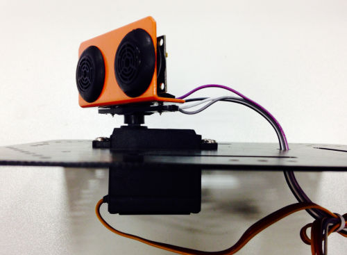
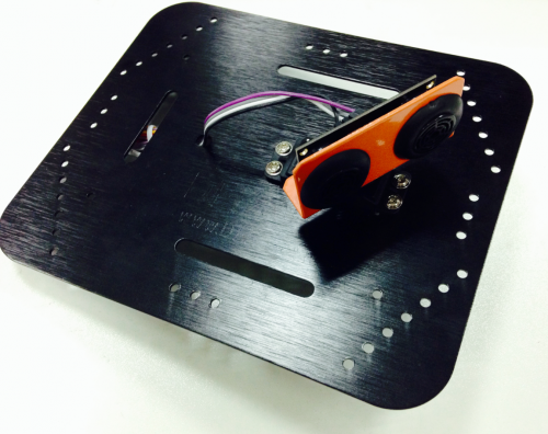
固定超声波位置
可以参看超声波扫描套件的安装手册固定舵机位置
![]()
![]()
STEP4: 调试超声波和舵机
- 硬件连接
这里我省去了上面电机部分的连接。不做重复说明了。

![]() 超声波、舵机控制
超声波、舵机控制
- 下载代码
下载代码之前需要安装Metro libray
如何加载库,可见链接
#include <Servo.h>
#include <Metro.h>
Metro measureDistance = Metro(50);
Metro sweepServo = Metro(20);
unsigned long actualDistance = 0;
Servo myservo; // create servo object to control a servo
int pos = 60;
int sweepFlag = 1;
int URPWM = 3; // PWM Output 0-25000US,Every 50US represent 1cm
int URTRIG= 10; // PWM trigger pin
uint8_t EnPwmCmd[4]={0x44,0x02,0xbb,0x01}; // distance measure command
void setup(){ // Serial initialization
myservo.attach(9);
Serial.begin(9600); // Sets the baud rate to 9600
SensorSetup();
}
void loop(){
if(measureDistance.check() == 1){
actualDistance = MeasureDistance();
// Serial.println(actualDistance);
// delay(100);
}
if(sweepServo.check() == 1){
servoSweep();
}
}
void SensorSetup(){
pinMode(URTRIG,OUTPUT); // A low pull on pin COMP/TRIG
digitalWrite(URTRIG,HIGH); // Set to HIGH
pinMode(URPWM, INPUT); // Sending Enable PWM mode command
for(int i=0;i<4;i++){
Serial.write(EnPwmCmd[i]);
}
}
int MeasureDistance(){ // a low pull on pin COMP/TRIG triggering a sensor reading
digitalWrite(URTRIG, LOW);
digitalWrite(URTRIG, HIGH); // reading Pin PWM will output pulses
unsigned long distance=pulseIn(URPWM,LOW);
if(distance==50000){ // the reading is invalid.
Serial.print("Invalid");
}else{
distance=distance/50; // every 50us low level stands for 1cm
}
return distance;
}
void servoSweep(){
if(sweepFlag ){
if(pos>=60 && pos<=120){
pos=pos+1; // in steps of 1 degree
myservo.write(pos); // tell servo to go to position in variable 'pos'
}
if(pos>119) sweepFlag = false; // assign the variable again
}else {
if(pos>=60 && pos<=120){
pos=pos-1;
myservo.write(pos);
}
if(pos<61) sweepFlag = true;
}
}
STEP5: 整机调试
- 固定上层板

![]() 固定上层板
固定上层板
2.下载整机调试代码
#include <Servo.h>
#include <Metro.h>
Metro measureDistance = Metro(50);
Metro sweepServo = Metro(20);
int speedPin_M1 = 5; //M1 Speed Control
int speedPin_M2 = 6; //M2 Speed Control
int directionPin_M1 = 4; //M1 Direction Control
int directionPin_M2 = 7; //M1 Direction Control
unsigned long actualDistance = 0;
Servo myservo; // create servo object to control a servo
int pos = 60;
int sweepFlag = 1;
int URPWM = 3; // PWM Output 0-25000US,Every 50US represent 1cm
int URTRIG= 10; // PWM trigger pin
uint8_t EnPwmCmd[4]={0x44,0x02,0xbb,0x01}; // distance measure command
void setup(){ // Serial initialization
myservo.attach(9);
Serial.begin(9600); // Sets the baud rate to 9600
SensorSetup();
}
void loop(){
if(measureDistance.check() == 1){
actualDistance = MeasureDistance();
// Serial.println(actualDistance);
// delay(100);
}
if(sweepServo.check() == 1){
servoSweep();
}
if(actualDistance <= 30){
myservo.write(90);
if(pos>=90){
// carBack(100,100);
//// Serial.println("carBack");
// delay(100);
carTurnRight(150,150);
// Serial.println("carTurnRight");
delay(100);
}else{
// carBack(100,100);
//// Serial.println("carBack");
// delay(100);
carTurnLeft(150,150);
// Serial.println("carTurnLeft");
delay(100);
}
}else{
carAdvance(70,70);
// Serial.println("carAdvance");
delay(100);
}
// carBack(150,150);
}
void SensorSetup(){
pinMode(URTRIG,OUTPUT); // A low pull on pin COMP/TRIG
digitalWrite(URTRIG,HIGH); // Set to HIGH
pinMode(URPWM, INPUT); // Sending Enable PWM mode command
for(int i=0;i<4;i++){
Serial.write(EnPwmCmd[i]);
}
}
int MeasureDistance(){ // a low pull on pin COMP/TRIG triggering a sensor reading
digitalWrite(URTRIG, LOW);
digitalWrite(URTRIG, HIGH); // reading Pin PWM will output pulses
unsigned long distance=pulseIn(URPWM,LOW);
if(distance==50000){ // the reading is invalid.
Serial.print("Invalid");
}else{
distance=distance/50; // every 50us low level stands for 1cm
}
return distance;
}
void carStop(){ // Motor Stop
digitalWrite(speedPin_M2,0);
digitalWrite(directionPin_M1,LOW);
digitalWrite(speedPin_M1,0);
digitalWrite(directionPin_M2,LOW);
}
void carTurnLeft(int leftSpeed,int rightSpeed){ //Turn Left
analogWrite (speedPin_M2,leftSpeed); //PWM Speed Control
digitalWrite(directionPin_M1,HIGH);
analogWrite (speedPin_M1,rightSpeed);
digitalWrite(directionPin_M2,HIGH);
}
void carTurnRight(int leftSpeed,int rightSpeed){ //Turn Right
analogWrite (speedPin_M2,leftSpeed);
digitalWrite(directionPin_M1,LOW);
analogWrite (speedPin_M1,rightSpeed);
digitalWrite(directionPin_M2,LOW);
}
void carBack(int leftSpeed,int rightSpeed){ //Move backward
analogWrite (speedPin_M2,leftSpeed);
digitalWrite(directionPin_M1,LOW);
analogWrite (speedPin_M1,rightSpeed);
digitalWrite(directionPin_M2,HIGH);
}
void carAdvance(int leftSpeed,int rightSpeed){ //Move forward
analogWrite (speedPin_M2,leftSpeed);
digitalWrite(directionPin_M1,HIGH);
analogWrite (speedPin_M1,rightSpeed);
digitalWrite(directionPin_M2,LOW);
}
void servoSweep(){
if(sweepFlag){
if(pos>=60 && pos<=120){
pos=pos+1; // in steps of 1 degree
myservo.write(pos); // tell servo to go to position in variable 'pos'
}
if(pos>119) sweepFlag = false; // assign the variable again
}
else {
if(pos>=60 && pos<=120){
pos=pos-1;
myservo.write(pos);
}
if(pos<61) sweepFlag = true;
}
}
你的专属小车就此诞生!![]() 购买海盗船基础套件 (SKU:ROB0022)
购买海盗船基础套件 (SKU:ROB0022)