SD2405 Real-Time clock Module(.NET Gadgeteer Compatible)
<img alt="" src="http://images.ncnynl.com/arduino/2016/350px-RTC_SD2405_Picture.jpg" width="350" height="317" class="thumbimage" /> <img src="http://images.ncnynl.com/arduino/2016/magnify-clip.png" width="15" height="11" alt="" />Real-Time clock
目录
1 概述
2 性能描述
3 引脚定义
4 硬件连接
5 例子程序
概述
SD2405 Real-Time clock Module内置晶振、IIC串行接口的高精度时钟。Arduino、Gadgeteer平台均可用。
性能描述
工作电压:5V
接口方式:IIC
工作温度:-40℃~+85℃
模块尺寸:31.00 × 36.00(mm)
引脚定义
连接arduino平台接口(排针接口):
1、+5:逻辑电压5V
2、G:电源负
3、SCL:IIC时钟输入引脚
4、SDA:IIC数据输入引脚
5、INT:报警中断输出引脚
Gadgeteer插座:
PIN1:3.3V
PIN2:5V
PIN3:INT
PIN4:NC
PIN5:NC
PIN6:NC
PIN7:NC
PIN8:SDA
PIN9:SCL
PIN10:G
硬件连接
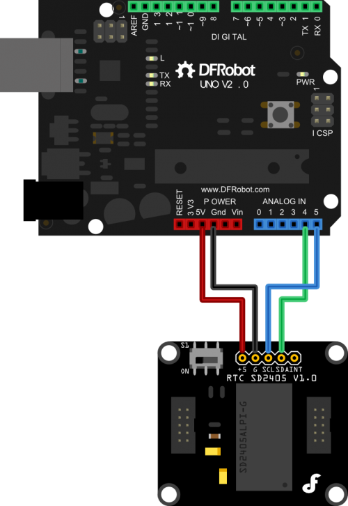
在这里选择Arduino 328作为控制器举例说明
选用杜邦线(公母头)作为连接线,将模块与328板子连接起来
杜邦线一端插在模块排针,另一端插在328板子,线序如下:
模块 ———— 328板子
+5 ———— 5V
G ———— GND
SDA ———— 4(模拟IO,4脚)
SCL ———— 5(模拟IO,5脚)
Dreamer系列直接用IDC10芯线连接模块和板子上的IIC接口(丝印是X Y I)即可
例子程序
#include <Wire.h>
#define RTC_Address 0x32 //RTC_Address
unsigned char date[7];
void setup()
{
Wire.begin();
Serial.begin(9600);
}
void loop()
{
I2CWriteDate();//Write the Real-time Clock
delay(100);
while(1)
{
I2CReadDate(); //Read the Real-time Clock
Data_process();//Process the data
delay(1000);//延时1S
}
}
//Read the Real-time data register of SD2403
void I2CReadDate(void)
{
unsigned char n=0;
Wire.requestFrom(RTC_Address,7);
while(Wire.available())
{
date[n++]=Wire.read();
}
delayMicroseconds(1);
Wire.endTransmission();
}
//Write the Real-time data register of SD2403
void I2CWriteDate(void)
{
WriteTimeOn();
Wire.beginTransmission(RTC_Address);
Wire.write(byte(0));//Set the address for writing
Wire.write(0x59);//second:59
Wire.write(0x01);//minute:1
Wire.write(0x95);//hour:15:00(24-hour format)
Wire.write(0x03);//weekday:Wednesday
Wire.write(0x26);//day:26th
Wire.write(0x12);//month:December
Wire.write(0x12);//year:2012
Wire.endTransmission();
Wire.beginTransmission(RTC_Address);
Wire.write(0x12); //Set the address for writing
Wire.write(byte(0));
Wire.endTransmission();
WriteTimeOff();
}
//The program for allowing to write to SD2400
void WriteTimeOn(void)
{
Wire.beginTransmission(RTC_Address);
Wire.write(0x10);//Set the address for writing as 10H
Wire.write(0x80);//Set WRTC1=1
Wire.endTransmission();
Wire.beginTransmission(RTC_Address);
Wire.write(0x0F);//Set the address for writing as OFH
Wire.write(0x84);//Set WRTC2=1,WRTC3=1
Wire.endTransmission();
}
//The program for forbidding writing to SD2400
void WriteTimeOff(void)
{
Wire.beginTransmission(RTC_Address);
Wire.write(0x0F); //Set the address for writing as OFH
Wire.write(byte(0));//Set WRTC2=0,WRTC3=0
Wire.write(byte(0));//Set WRTC1=0
Wire.endTransmission();
}
//Process the time_data
void Data_process(void)
{
unsigned char i;
for(i=0;i<7;i++)
{
if(i!=2)
date[i]=(((date[i]&0xf0)>>4)10)+(date[i]&0x0f);
else
{
date[2]=(date[2]&0x7f);
date[2]=(((date[2]&0xf0)>>4)10)+(date[2]&0x0f);
}
}
// Use the serial monitor to see information being transmitted
Serial.print("Sec = ");//second
Serial.print(date[
Serial.println();
}
![]() 购买SD2405 Real-Time clock Module(.NET Gadgeteer Compatible) (SKU:TOY0021)
购买SD2405 Real-Time clock Module(.NET Gadgeteer Compatible) (SKU:TOY0021)