DS1307 时钟模块 V1.1
<img alt="IMGP9616.jpg" src="http://images.ncnynl.com/arduino/2016/250px-IMGP9616.jpg" width="250" height="250" />
目录
1 简介
2 产品参数
3 应用
4 使用教程
4.1 连线图
4.2 样例代码
4.3 结果
5 疑难解答
6 更多
简介
这款DS1307时钟模块是由我们的设计师Waiman开发的高质量时钟模块。该模块出厂时就附带电池(CR1225 41MAH),并已经烧录了准确的北京时间(MST)。该模块在不具备外接5V电源的情况下,最小使用寿命为9年,但是一般能达到17年。DS1307芯片通过I2C协议通信。
不同于一般的时钟模块,DFR0151具备以下特色功能:
模块集成了I2C EEPROM芯片(24C32)和DS18B20传感器接口。I2C EEPROM具备4KB的内存,使得模块在存储数据时大大节省时间和处理器资源。
该模块还为DS18B20内嵌了上拉电阻,使你更方便的增加温度监控功能。在板子的右下角具备3P的DS18B20接口,用户可以使用我们的DFR0024数字温度传感器模块或者DFR0198防水温度传感器。
产品参数
工作电压:5V
左右双I2C端口
时间格式:小时-分钟-秒 AM/PM,日/月/星期/年
瑞年补偿计算
保证准确日期到2100年
包括备份电池
1Hz输出插口
56字节的非易失性内存
4KB的只读内存(EEPROM)
内嵌DS18B20的上拉电阻
尺寸:28258mm
应用
实时时间监控系统
定时器
使用教程
连线图

引脚说明
GND——GND
VCC——5V
SDA——A4
SCL——A5
DS——D2
样例代码
在编译程序之前,请先下载并安装DS1307库文件
库安装
#include <Wire.h>
#include <DS1307.h>
/*
about set time:
format: year,month,day,week,hour,min,sec
example: 14,03,25,02,13,55,10 2014.03.25 tuesday 13:55:10
*/
String comdata = "";
int mark=0;
//store the current time data
int rtc[7];
//store the set time data
byte rr[7];
//light pin
int ledPin = 13;
//initial light
void setup()
{
DDRC |= _BV(2) | _BV(3); // POWER:Vcc Gnd
PORTC |= _BV(3); // VCC PINC3
pinMode(ledPin, OUTPUT);
//initial baudrate
Serial.begin(9600);
//get current time
RTC.get(rtc, true);
//if time is wrong reset to default time
if (rtc[6] < 12) {
//stop rtc time
RTC.stop();
RTC.set(DS1307_SEC, 1);
RTC.set(DS1307_MIN, 27);
RTC.set(DS1307_HR, 01);
RTC.set(DS1307_DOW, 7);
RTC.set(DS1307_DATE, 12);
RTC.set(DS1307_MTH, 2);
RTC.set(DS1307_YR, 12);
//start rtc time
RTC.start();
}
//RTC.SetOutput(LOW);
//RTC.SetOutput(HIGH);
//RTC.SetOutput(DS1307_SQW1HZ);
//RTC.SetOutput(DS1307_SQW4KHZ);
//RTC.SetOutput(DS1307_SQW8KHZ);
RTC.SetOutput(DS1307_SQW32KHZ);
}
void loop()
{
int i;
//get current time
RTC.get(rtc, true);
//print current time format : year month day week hour min sec
for (i = 0; i < 7; i++)
{
Serial.print(rtc[i]);
Serial.print(" ");
}
//blink the light
Serial.println();
digitalWrite(ledPin, HIGH);
delay(500);
digitalWrite(ledPin, LOW);
delay(500);
//
int j = 0;
//read all the data
while (Serial.available() > 0)
{
comdata += char(Serial.read());
delay(2);
mark = 1;
}
//if data is all collected,then parse it
if (mark == 1)
{
Serial.println(comdata);
Serial.println(comdata.length());
//parse data
for (int i = 0; i < comdata.length() ; i++)
{
//if the byte is ',' jump it,and parse next value
if (comdata[i] == ',')
{
j++;
}
else
{
rr[j] = rr[j] * 10 + (comdata[i] - '0');
}
}
comdata = String("");
RTC.stop();
RTC.set(DS1307_SEC, rr[6]);
RTC.set(DS1307_MIN, rr[5]);
RTC.set(DS1307_HR, rr[4]);
RTC.set(DS1307_DOW, rr[3]);
RTC.set(DS1307_DATE, rr[2]);
RTC.set(DS1307_MTH, rr[1]);
RTC.set(DS1307_YR, rr[
}
结果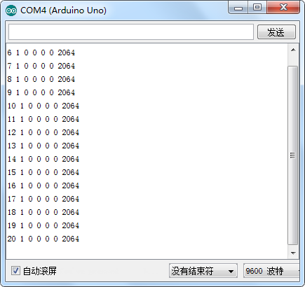 疑难解答
电脑时间实时更新
疑难解答
电脑时间实时更新
更多问题及有趣的应用,请访问论坛
更多
Real Time Clock Module (DS1307) V1.0
Arduino Library
Schematic
DS1307 Datasheet
Forum discussion about EEPROM
![]()