用MEGA2560给MEGA328P刷bootloader经验分享!
前天手贱把自己的UNO R3板子引导给写坏了,手上又没有USBASP来恢复。不过有一个MEGA2560的板子。在论坛里看到有人用UNO的板子给UNO的板子写bootloader的例子,在想能不能用mega2560来给UNO写呢?
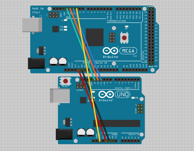
说干就干,打开arduino IDE 软件。文件--示例--ArduinoISP 。将这个示例下载进MEGA2560的开发板,如下接线:
2015-11-16 15:59 上传
(104.84 KB)
失败的
然后选工具--编程器--arduino as isp--板子选uno ,然后各种失败!包括各个板子型号全部选一遍都是失败。reset线上加10uf电解电容,也失败。
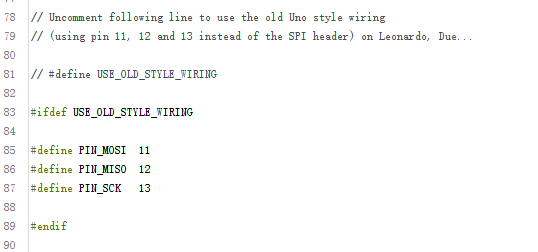
无奈之下,去看前面给MEGA2560下载的那个ArduinoISP的文件里写的到底是什么东西,发现MEGA2560的引脚应该不是跟UNO一样,而是有自己的MISO,MOSI,SCK引脚。如果直接烧网上所说的ArduinoISP。那么引脚就有问题。于是尝试自己修改引脚。具体步骤如下:
找到如下代码位置:
2015-11-16 16:06 上传
(13.2 KB)
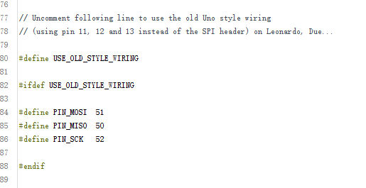
按照如下修改:
2015-11-16 16:06 上传
(13.16 KB)
意思大概就是使用自定义的引脚。为什么是5150 52呢,是查MEGA2560的引脚手册知道的。
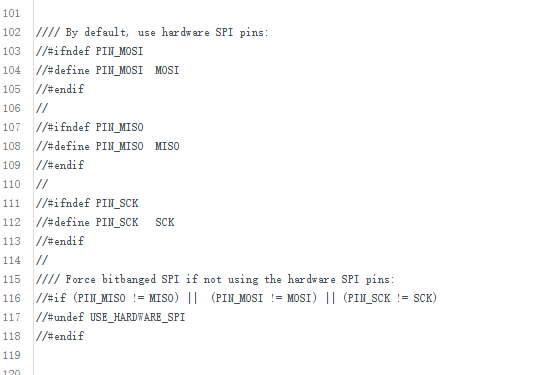
为了保险起见,我将如下代码也注释掉了
2015-11-16 16:08 上传
(19.17 KB)
然后下载进mega2560的板子里。重新按照如下接线:
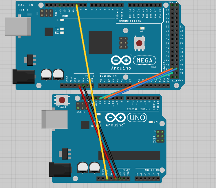
2015-11-16 16:10 上传
(129.27 KB)
也就是将UNO的11接2560的51。12接50,13接52。RESET线不变任然接10号线。
重新选择工具---编程器--- -arduino as isp ---板子选

2015-11-16 16:13 上传
(4.42 KB)
(因为R3增强板使用的是CH340T直接做USB转串口的,所以UNO不能用)。
然后工具--烧录引导程序--成功。
UNO的13号灯会一闪一闪。
最后把我修改好的ArduinoISP代码附上,直接复制过去使用也行。
ARDUINO 代码复制打印下载
// ArduinoISP// Copyright (c) 2008-2011 Randall Bohn// If you require a license, see// [url=http://www.opensource.org/licenses/bsd-license.php]http://www.opensource.org/licenses/bsd-license.php[/url]//// This sketch turns the Arduino into a AVRISP// using the following arduino pins://// Pin 10 is used to reset the target microcontroller.//// By default, the hardware SPI pins MISO, MOSI and SCK pins are used// to communicate with the target. On all Arduinos, these pins can be found// on the ICSP/SPI header://// MISO °. . 5V (!) Avoid this pin on Due, Zero...// SCK . . MOSI// . . GND//// On some Arduinos (Uno,...), pins MOSI, MISO and SCK are the same pins// as digital pin 11, 12 and 13, respectively. That is why many tutorials// instruct you to hook up the target to these pins. If you find this wiring// more practical, have a define USE_OLD_STYLE_WIRING. This will work even// even when not using an Uno. (On an Uno this is not needed).//// Alternatively you can use any other digital pin by configuring software ('BitBanged')// SPI and having appropriate defines for PIN_MOSI, PIN_MISO and PIN_SCK.// // IMPORTANT: When using an Arduino that is not 5V tolerant (Due, Zero, ...)// as the programmer, make sure to not expose any of the programmer's pins to 5V.// A simple way to accomplish this is to power the complete system (programmer// and target) at 3V3.//// Put an LED (with resistor) on the following pins:// 9: Heartbeat - shows the programmer is running// 8: Error - Lights up if something goes wrong (use red if that makes sense)// 7: Programming - In communication with the slave//#include "Arduino.h"#undef SERIAL#define PROG_FLICKER true// Configure SPI clock (in Hz).// E.g. for an attiny @128 kHz: the datasheet states that both the high// and low spi clock pulse must be > 2 cpu cycles, so take 3 cycles i.e.// divide target f_cpu by 6:// #define SPI_CLOCK (128000/6)//// A clock slow enough for an attiny85 @ 1MHz, is a reasonable default:#define SPI_CLOCK (1000000/6)// Select hardware or software SPI, depending on SPI clock.// Currently only for AVR, for other archs (Due, Zero,...),// hardware SPI is probably too fast anyway.#if defined(ARDUINO_ARCH_AVR)#if SPI_CLOCK > (F_CPU / 128)#define USE_HARDWARE_SPI#endif#endif// Configure which pins to use:// The standard pin configuration.#ifndef ARDUINO_HOODLOADER2 #define RESET 10 // Use pin 10 to reset the target rather than SS#define LED_HB 9#define LED_ERR 8#define LED_PMODE 7// Uncomment following line to use the old Uno style wiring// (using pin 11, 12 and 13 instead of the SPI header) on Leonardo, Due...#define USE_OLD_STYLE_WIRING //此处别忘记取消注释#ifdef USE_OLD_STYLE_WIRING#define PIN_MOSI 51 //mega2560的MOSI#define PIN_MISO 50 //mega2560的MISO #define PIN_SCK 52 //mega2560的SCK#endif// HOODLOADER2 means running sketches on the atmega16u2 // serial converter chips on Uno or Mega boards.// We must use pins that are broken out:#else #define RESET 10#define LED_HB 7#define LED_ERR 6#define LED_PMODE 5#endif//// By default, use hardware SPI pins://#ifndef PIN_MOSI//#define PIN_MOSI MOSI//#endif////#ifndef PIN_MISO//#define PIN_MISO MISO//#endif////#ifndef PIN_SCK//#define PIN_SCK SCK//#endif////// Force bitbanged SPI if not using the hardware SPI pins://#if (PIN_MISO != MISO) ||(PIN_MOSI != MOSI) || (PIN_SCK != SCK)//#undef USE_HARDWARE_SPI//#endif// Configure the serial port to use.//// Prefer the USB virtual serial port (aka. native USB port), if the Arduino has one:// - it does not autoreset (except for the magic baud rate of 1200).// - it is more reliable because of USB handshaking.//// Leonardo and similar have an USB virtual serial port: 'Serial'.// Due and Zero have an USB virtual serial port: 'SerialUSB'.//// On the Due and Zero, 'Serial' can be used too, provided you disable autoreset.// To use 'Serial': #define SERIAL Serial#ifdef SERIAL_PORT_USBVIRTUAL#define SERIAL SERIAL_PORT_USBVIRTUAL#else#define SERIAL Serial#endif// Configure the baud rate:#define BAUDRATE 19200// #define BAUDRATE 115200// #define BAUDRATE 1000000#define HWVER 2#define SWMAJ 1#define SWMIN 18// STK Definitions#define STK_OK 0x10#define STK_FAILED0x11#define STK_UNKNOWN 0x12#define STK_INSYNC0x14#define STK_NOSYNC0x15#define CRC_EOP 0x20 //ok it is a space...void pulse(int pin, int times);#ifdef USE_HARDWARE_SPI#include "SPI.h"#else#define SPI_MODE0 0x00class SPISettings {public:// clock is in HzSPISettings(uint32_t clock, uint8_t bitOrder, uint8_t dataMode) : clock(clock){ (void) bitOrder; (void) dataMode;};private:uint32_t clock;friend class BitBangedSPI;};class BitBangedSPI {public:void begin() { digitalWrite(PIN_SCK, LOW); digitalWrite(PIN_MOSI, LOW); pinMode(PIN_SCK, OUTPUT); pinMode(PIN_MOSI, OUTPUT); pinMode(PIN_MISO, INPUT);}void beginTransaction(SPISettings settings) { pulseWidth = (500000 + settings.clock - 1) / settings.clock; if (pulseWidth == 0) pulseWidth = 1;}void end() {}uint8_t transfer (uint8_t b) { for (unsigned int i = 0; i < 8; ++i) { digitalWrite(PIN_MOSI, (b & 0x80) ? HIGH : LOW); digitalWrite(PIN_SCK, HIGH); delayMicroseconds(pulseWidth); b = (b << 1) | digitalRead(PIN_MISO); digitalWrite(PIN_SCK, LOW); // slow pulse delayMicroseconds(pulseWidth); } return b;}private:unsigned long pulseWidth; // in microseconds};static BitBangedSPI SPI;#endifvoid setup() {SERIAL.begin(BAUDRATE);pinMode(LED_PMODE, OUTPUT);pulse(LED_PMODE, 2);pinMode(LED_ERR, OUTPUT);pulse(LED_ERR, 2);pinMode(LED_HB, OUTPUT);pulse(LED_HB, 2);}int error = 0;int pmode = 0;// address for reading and writing, set by 'U' commandunsigned int here;uint8_t buff[256]; // global block storage#define beget16(addr) (*addr * 256 + *(addr+1) )typedef struct param {uint8_t devicecode;uint8_t revision;uint8_t progtype;uint8_t parmode;uint8_t polling;uint8_t selftimed;uint8_t lockbytes;uint8_t fusebytes;uint8_t flashpoll;uint16_t eeprompoll;uint16_t pagesize;uint16_t eepromsize;uint32_t flashsize;}parameter;parameter param;// this provides a heartbeat on pin 9, so you can tell the software is running.uint8_t hbval = 128;int8_t hbdelta = 8;void heartbeat() {static unsigned long last_time = 0;unsigned long now = millis();if ((now - last_time) < 40) return;last_time = now;if (hbval > 192) hbdelta = -hbdelta;if (hbval < 32) hbdelta = -hbdelta;hbval += hbdelta;analogWrite(LED_HB, hbval);}static bool rst_active_high;void reset_target(bool reset) {digitalWrite(RESET, ((reset && rst_active_high) || (!reset && !rst_active_high)) ? HIGH : LOW);}void loop(void) {// is pmode active?if (pmode) { digitalWrite(LED_PMODE, HIGH);} else { digitalWrite(LED_PMODE, LOW);}// is there an error?if (error) { digitalWrite(LED_ERR, HIGH);} else { digitalWrite(LED_ERR, LOW);}// light the heartbeat LEDheartbeat();if (SERIAL.available()) { avrisp();}}uint8_t getch() {while (!SERIAL.available());return SERIAL.read();}void fill(int n) {for (int x = 0; x < n; x++) { buff[x] = getch();}}#define PTIME 30void pulse(int pin, int times) {do { digitalWrite(pin, HIGH); delay(PTIME); digitalWrite(pin, LOW); delay(PTIME);} while (times--);}void prog_lamp(int state) {if (PROG_FLICKER) { digitalWrite(LED_PMODE, state);}}uint8_t spi_transaction(uint8_t a, uint8_t b, uint8_t c, uint8_t d) {SPI.transfer(a);SPI.transfer(b);SPI.transfer(c);return SPI.transfer(d);}void empty_reply() {if (CRC_EOP == getch()) { SERIAL.print((char)STK_INSYNC); SERIAL.print((char)STK_OK);} else { error++; SERIAL.print((char)STK_NOSYNC);}}void breply(uint8_t b) {if (CRC_EOP == getch()) { SERIAL.print((char)STK_INSYNC); SERIAL.print((char)b); SERIAL.print((char)STK_OK);} else { error++; SERIAL.print((char)STK_NOSYNC);}}void get_version(uint8_t c) {switch (c) { case 0x80: breply(HWVER); break; case 0x81: breply(SWMAJ); break; case 0x82: breply(SWMIN); break; case 0x93: breply('S'); // serial programmer break; default: breply();}}void set_parameters() {// call this after reading paramter packet into buff[]param.devicecode = buff[];param.revision = buff[1];param.progtype = buff[2];param.parmode = buff[3];param.polling = buff[4];param.selftimed= buff[5];param.lockbytes= buff[6];param.fusebytes= buff[7];param.flashpoll= buff[8];// ignore buff[9] (= buff[8])// following are 16 bits (big endian)param.eeprompoll = beget16(&buff[10]);param.pagesize = beget16(&buff[12]);param.eepromsize = beget16(&buff[14]);// 32 bits flashsize (big endian)param.flashsize = buff[16] * 0x01000000 + buff[17] * 0x00010000 + buff[18] * 0x00000100 + buff[19];// avr devices have active low reset, at89sx are active highrst_active_high = (param.devicecode >= 0xe0);}void start_pmode() {// Reset target before driving PIN_SCK or PIN_MOSI// SPI.begin() will configure SS as output,// so SPI master mode is selected.// We have defined RESET as pin 10,// which for many arduino's is not the SS pin.// So we have to configure RESET as output here,// (reset_target() first sets the correct level)reset_target(true);pinMode(RESET, OUTPUT);SPI.begin();SPI.beginTransaction(SPISettings(SPI_CLOCK, MSBFIRST, SPI_MODE0));// See avr datasheets, chapter "SERIAL_PRG Programming Algorithm":// Pulse RESET after PIN_SCK is low:digitalWrite(PIN_SCK, LOW);delay(20); // discharge PIN_SCK, value arbitrally chosenreset_target(false);// Pulse must be minimum 2 target CPU clock cycles// so 100 usec is ok for CPU speeds above 20KHzdelayMicroseconds(100);reset_target(true);// Send the enable programming command:delay(50); // datasheet: must be > 20 msecspi_transaction(0xAC, 0x53, 0x00, 0x00);pmode = 1;}void end_pmode() {SPI.end();// We're about to take the target out of reset// so configure SPI pins as inputpinMode(PIN_MOSI, INPUT);pinMode(PIN_SCK, INPUT);reset_target(false);pinMode(RESET, INPUT);pmode = 0;}void universal() {uint8_t ch;fill(4);ch = spi_transaction(buff[
via - 极客工坊