arduino教程系列40-Arduino Uno + BMA180三轴加速度计演示实验
今天想起了自己手上有了一个BMA180加速度传感器模块,论坛里之前弘毅已经写过ADXL345的模块使用方法,由于这些姿态方面的模块现在市面上已经不算少的了,比如ITG3200、ADXL345、ADXL335、HMC5883L、MPU6050、BMP085、MMA7361等等好多的这种芯片,这些芯片目前发现用的比较多的领域,应该是飞控方面的了,而我发现基于Arduino 的四轴方面的飞控在国内没多少,我也想多学习学习前辈的经验,可是见没多少资源,再次希望大家懂玩的朋友一起弄弄飞控的相关传感器的运用是不错的哦!接下来我写一下我在学习Bma180的一些学习笔记,如有什么错误请指出,谢谢!
1、概述
博世BMA180三轴超高性能数字加速度计,它提供了14位数字输出通过一个4线SPI或2线I 2 C接口。满量程的测量范围可设定为±1g平衡,1.5G,2G,3G,4G,8G或16G。其他功能还包括可编程唤醒,低g和高g检测,自来水检测,边坡检测,自检能力。该传感器还具有两种工作模式:低噪音,低功耗 BMA180采用3x3mm 12引脚LGA封装在一个微小的。该传感器可在1.62至3.6V之间的VDD和1.2至3.6V的VDDIO的供电,将通常只消耗650uA的标准模式。
2、一分场板是BMA180 这里。
各种各样的测算范围(±1g平衡,1.5G,2G,3G,4G,8G和16G)
14 - 位或12位ADC转换
2个可选的I 2 C地址
集成可编程数字滤波器(没有必要的外部元件)
8个低通滤波器
1高通滤波器
1带通滤波器
可编程中断功能:
唤醒
低g检测
高g检测
点击传感
边坡检测
2个主要的标准模式:低噪声和低功耗
睡眠模式
唤醒模式
自检能力
3、应用:
BMA180 是一款超高性能三轴数字加速度传感器, 主要是针对低能消费市场的应用。
BMA180具有高测量精度的3个互相垂直的轴的加速度传感器,因此在Sen-Ses倾斜、运动、 冲击和振动在手机、掌上电脑、电脑周边、人机交换-面孔、虚拟现实的特性和游戏控制 器都有相应的应用.
想知道更详细的资料,可以查询此芯片的datasheet哦。
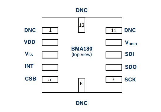
4、BMA180的芯片引脚图

2012-6-5 15:25 上传
(23.17 KB)
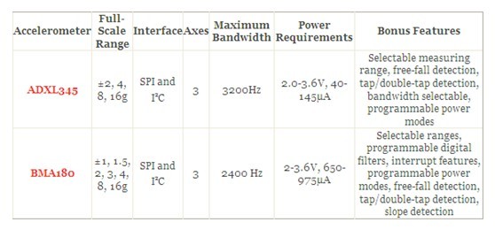
5、BMA180与ADXL345相比较:

2012-6-5 15:25 上传
(34.7 KB)
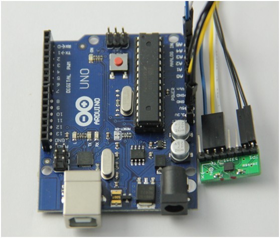
6、本实验我们所用到的主控板还是Arduino Uno ,下面我们来看一下与BMA180连接时的连线图:

2012-6-5 15:25 上传
(18.12 KB)

2012-6-5 15:25 上传
(59.08 KB)
7、通过以上的连接后,我们可以进行代码的调试、编译了,在这里我们提供的代码是演示所用的代码,需其他用途,需要自己去写代码!
#include <Wire.h>

void setup()
{
  Serial.begin(115200);
  Wire.begin();

  Serial.println("Demo started, initializing sensors");

  AccelerometerInit();
//  GyroInit();

  Serial.println("Sensors have been initialized");
}

void AccelerometerInit()
{
  Wire.beginTransmission(0x40); // address of the accelerometer
  // reset the accelerometer
  Wire.send(0x10);
  Wire.send(0xB6);
  Wire.endTransmission();
  delay(10);

  Wire.beginTransmission(0x40); // address of the accelerometer
  // low pass filter, range settings
  Wire.send(0x0D);
  Wire.send(0x10);
  Wire.endTransmission();

  Wire.beginTransmission(0x40); // address of the accelerometer
  Wire.send(0x20); // read from here
  Wire.endTransmission();
  Wire.requestFrom(0x40, 1);
  byte data = Wire.receive();
  Wire.beginTransmission(0x40); // address of the accelerometer
  Wire.send(0x20);
  Wire.send(data & 0x0F); // low pass filter to 10 Hz
  Wire.endTransmission();

  Wire.beginTransmission(0x40); // address of the accelerometer
  Wire.send(0x35); // read from here
  Wire.endTransmission();
  Wire.requestFrom(0x40, 1);
  data = Wire.receive();
  Wire.beginTransmission(0x40); // address of the accelerometer
  Wire.send(0x35);
  Wire.send((data & 0xF1) | 0x04); // range +/- 2g
  Wire.endTransmission();
}

void AccelerometerRead()
{
  Wire.beginTransmission(0x40); // address of the accelerometer
  Wire.send(0x02); // set read pointer to data
  Wire.endTransmission();
  Wire.requestFrom(0x40, 6);

  // read in the 3 axis data, each one is 16 bits
  // print the data to terminal
  Serial.print("Accelerometer: X = ");
  short data = Wire.receive();
  data += Wire.receive() << 8;
  Serial.print(data);
  Serial.print(" , Y = ");
  data = Wire.receive();
  data += Wire.receive() << 8;
  Serial.print(data);
  Serial.print(" , Z = ");
  data = Wire.receive();
  data += Wire.receive() << 8;
  Serial.print(data);
  Serial.println();
}

/*void GyroInit()
{
  Wire.beginTransmission(0x69); // address of the gyro
  // reset the gyro
  Wire.send(0x3E);
  Wire.send(0x80);
  Wire.endTransmission();

  Wire.beginTransmission(0x69); // address of the gyro
  // low pass filter 10 Hz
  Wire.send(0x16);
  Wire.send(0x1D);
  Wire.endTransmission();

  Wire.beginTransmission(0x69); // address of the gyro
  // use internal oscillator
  Wire.send(0x3E);
  Wire.send(0x01);
  Wire.endTransmission();
}

void GyroRead()
{
  Wire.beginTransmission(0x69); // address of the gyro
  Wire.send(0x1D); // set read pointer
  Wire.endTransmission();

  Wire.requestFrom(0x69, 6);

  // read in 3 axis of data, 16 bits each, print to terminal
  short data = Wire.receive() << 8;
  data += Wire.receive();
  Serial.print("Gyro: X = ");
  Serial.print(data);
  Serial.print(" , Y = ");
  data = Wire.receive() << 8;
  data += Wire.receive();
  Serial.print(data);
  Serial.print(" , Z = ");
  data = Wire.receive() << 8;
  data += Wire.receive();
  Serial.print(data);
  Serial.println();
} */

void loop()
{
  AccelerometerRead();
//  GyroRead();

  delay(500); // slow down output
}
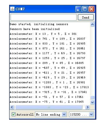
通过串口监视窗口我们可以看到结果如下:

2012-6-5 15:25 上传
(59.66 KB)
网盘附件下载http://pan.baidu.com/s/1dExdYV3
datasheet: BMA180.pdf (1.16 MB)
via - 极客工坊